

Thermal structure for electric devices
a technology of electric devices and thermal structures, applied in the field of thermal modules, can solve the problems of copper reduction, overweight, cost, complexity of computer systems, etc., and achieve the effect of reducing copper consumption, reducing copper consumption, and increasing manufacturing costs
- Summary
- Abstract
- Description
- Claims
- Application Information
AI Technical Summary
Benefits of technology
Problems solved by technology
Method used
Image

Examples
Embodiment Construction
[0016]The following provides exemplary embodiments of the present invention with reference to the accompanying drawings.
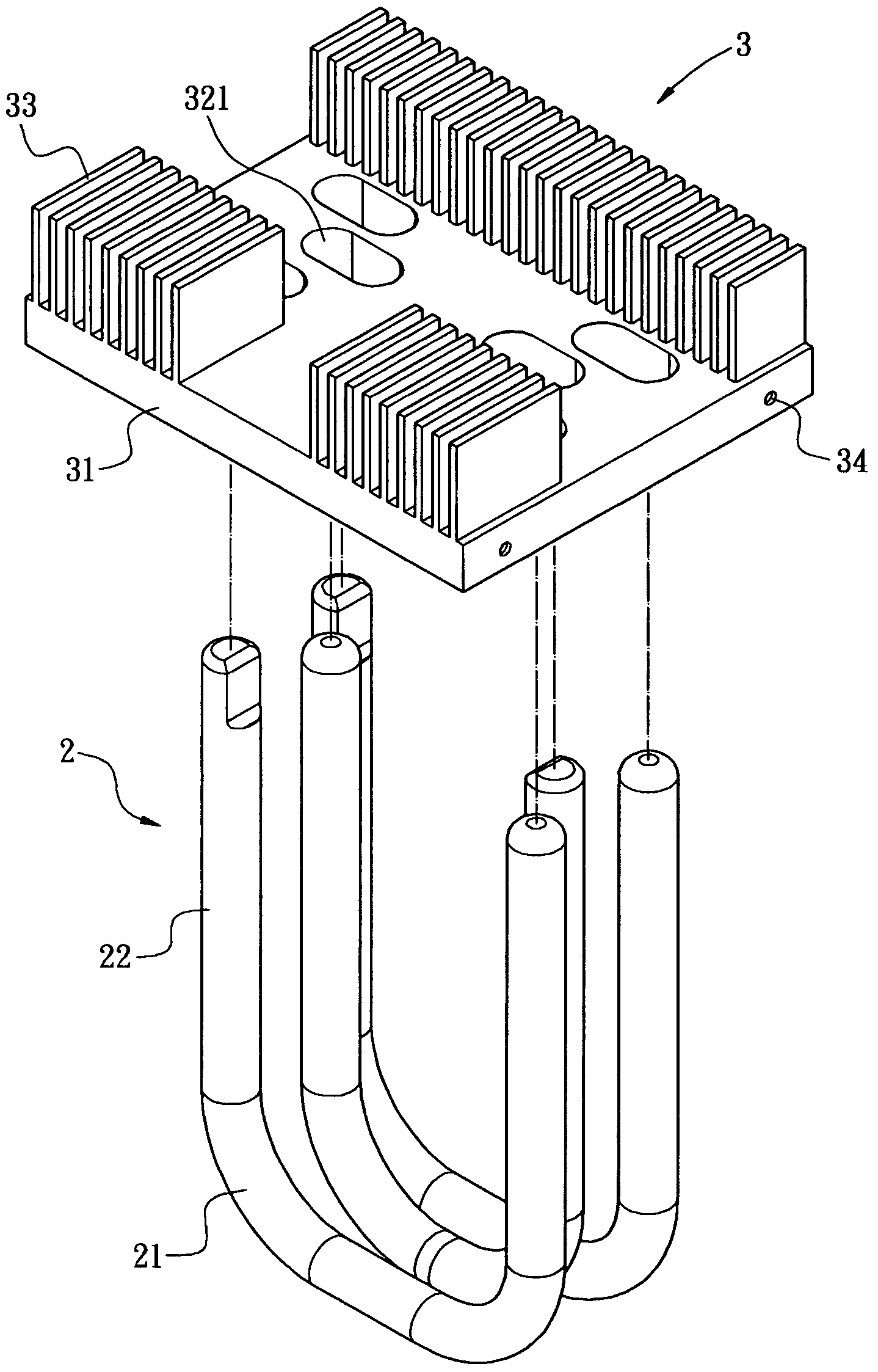
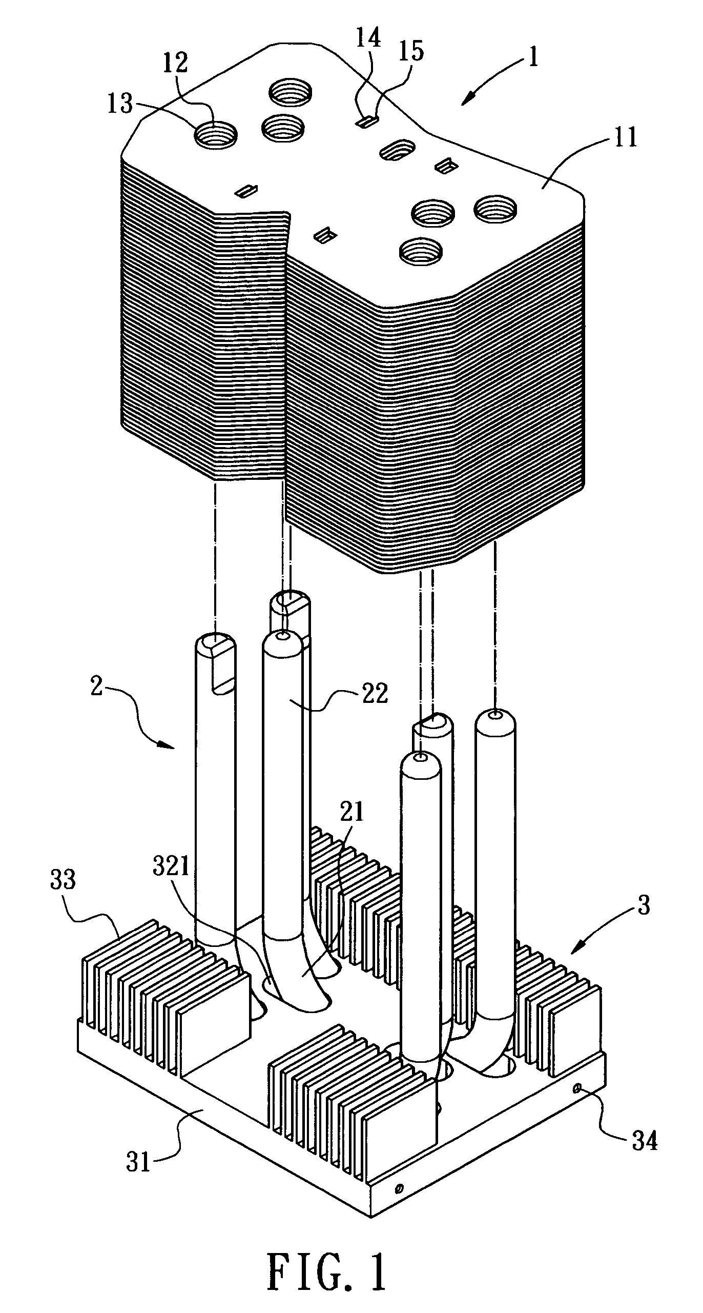
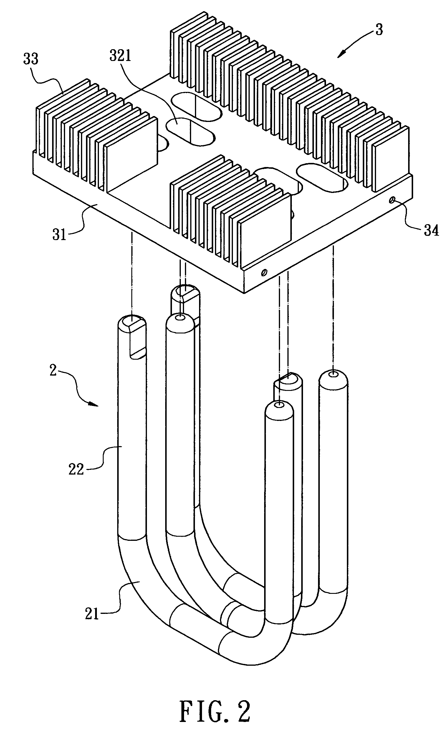
[0017]In FIGS. 1 trough 3, a thermal module comprising a thermal body 1, at least one thermal tube 2, and a holding part 3 is provided.
[0018]The thermal body 1 is made of stacking fins 11, which comprises aluminum, copper, or other metal with excellent thermal conductivity. A plurality of holes 12 are formed through each of the fins 11. Ring walls 13 are formed surrounding the top of the holes 12. A plurality of rectangle holes 14 are formed in the middle of each of the fins 11. A retaining wall 15 bending upward is formed on one side of each of the rectangle holes 14. The height of the retaining wall 15 is the same with that of the ring wall 13, such that the distance serving as a thermal fluid between each two of the fins 11 is always the same after assembling of the fins 11. In another embodiment, the thermal body 1 is made by extruding (not shown).
[0019]The the...
PUM
 Abstract
Description
Claims
Application Information