Apparatus with a series of resonator structures situated near an optical waveguide for manipulating optical pulses

a technology of optical waveguides and resonators, applied in the field of optical waveguides, can solve the problems of long lengths of optical waveguides that are either too slow and/or require long lengths of optical waveguides to function, and achieve the effects of easy integration with other photonic technologies, enhanced nonlinearity, and small siz

Inactive Publication Date: 2007-07-17
UNIVERSITY OF ROCHESTER
View PDF11 Cites 70 Cited by
  • Summary
  • Abstract
  • Description
  • Claims
  • Application Information

AI Technical Summary

Benefits of technology

[0012]The embodiments of the present invention provides a number of advantages. For example, invention produces a dispersion that is about seven orders of magnitude greater than that of conventional mediums, such as optical fiber, with similarly enhanced nonlinearity, resulting in enabling devices that can be made very small and which can be easily integrated with other photonic technologies. Further, the present invention enables very fast switching, routing, demultiplexing, and / or pulse compression and / or stretching, for example, to take place using the resonators 12(1)–12(n) in the manner described above.

Problems solved by technology

While current waveguide arrangements used in these applications work, they result in devices that are either too slow and / or require long lengths of optical waveguides to function.

Method used


Image

  • Apparatus with a series of resonator structures situated near an optical waveguide for manipulating optical pulses
  • Apparatus with a series of resonator structures situated near an optical waveguide for manipulating optical pulses
  • Apparatus with a series of resonator structures situated near an optical waveguide for manipulating optical pulses

Examples


Embodiment Construction

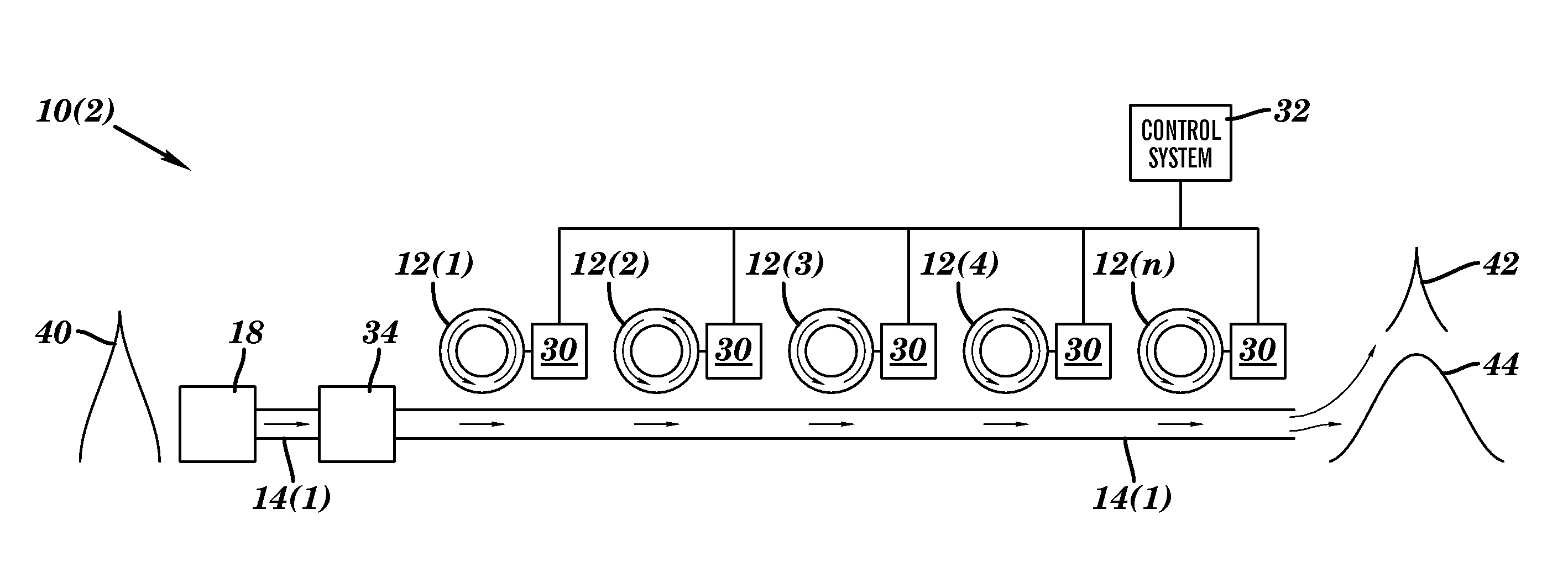
[0025]Systems 10(1)–10(2) for manipulating optical pulses in accordance with different embodiments of the present invention are illustrated in FIGS. 1 and 4. The systems 10(1)–10(2) each include resonators 12(1)–12(n), one or more optical waveguides 14, and an input light source 18. The systems 10(1)–10(2) provides a number of advantages, such as systems 10(1)–10(2) which can be made very small and which can be easily integrated with other photonic technologies. Further, the systems 10(1)–10(2) enable very fast switching, routing, demultiplexing, and / or pulse compression and / or stretching.

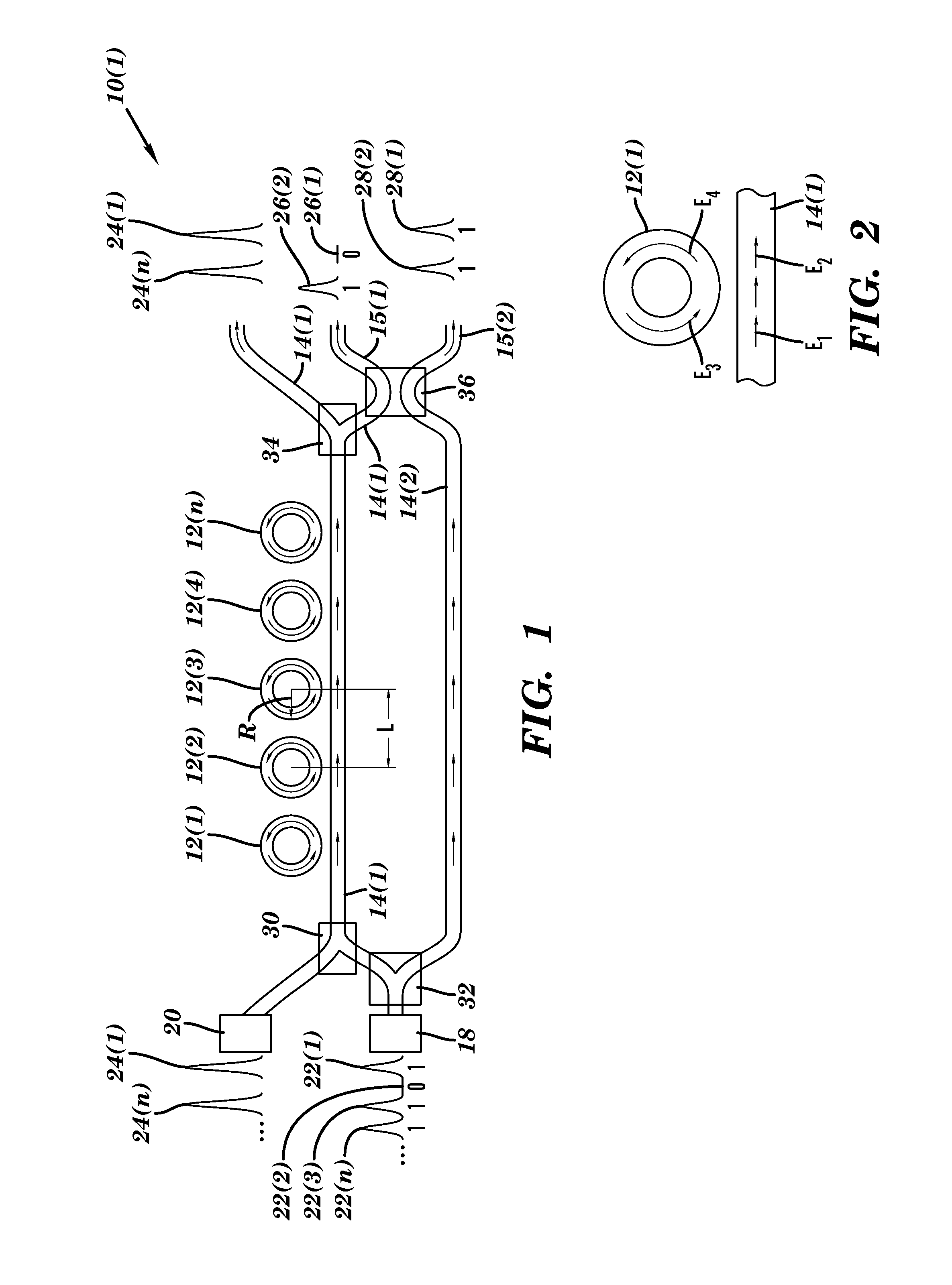
[0026]Referring to FIG. 1, a system 10(1) for manipulating optical pulses to implement an optical switch in accordance with one embodiment of the present invention is illustrated. In this particular embodiment, the optical switch system 10(1) includes resonators 12(1)–12(n), waveguides 14(1) and 14(2), output waveguides 15(1) and 15(2), input light source 18, control light source 20, combiner 30, b...


PUM


Abstract

Systems and method for manipulating optical pulses to implement an optical switch and for pulse shaping (e.g., pulse compression and / or compression) are disclosed. In one embodiment, the system comprises an optical switch apparatus that includes a plurality of resonators optically coupled to a waveguide, two output waveguides, an input light source, a control light source. The system selects some of the input signals emitted from the input light course using control signals emitted from the control light source to route to one of the output waveguides. In another embodiment, the system includes a waveguide optically coupled to a plurality of resonators, input light source, optional resonator modules that can change the refractive index of the resonators, and an optional amplifier. This system can change the shape of the pulses by changing a number of parameters, such as the incoming pulse amplitude and / or the refractive index of the resonators.

Description

[0001]This application claims the benefit of U.S. Provisional Patent Application Ser. No. 60 / 367,062 filed on Mar. 21, 2002, which is herein incorporated by reference.[0002]This invention was developed with Government funding from the Air Force Office of Scientific Research under grant F49620-00-1-1061 and the Defense Advanced Research Projects Agency under grant MDA972-00-1-0021. The U.S. Government may have certain rights in this invention.FIELD OF THE INVENTION[0003]This invention relates generally to optical waveguides and, more particularly, to an apparatus with a series of resonator structures situated near an optical waveguide for manipulating optical pulses, such as for pulse stretching, compression and switching, and for creating pulse trains.BACKGROUND OF THE INVENTION[0004]In general, optical waveguides are formed of a length of transparent material that is surrounded by another material which has a lower index of refraction. Light beams propagating within the waveguide t...

Claims


Application Information

Patent Timeline
IPC IPC(8): G02B6/26G02B6/42G02B6/12G02B6/122G02B6/125G02B6/136G02B6/35
CPCG02B6/12004G02B6/12007G02B6/122G02B6/1221G02B6/125G02B6/136G02B2006/12147
Inventor BOYD, ROBERT W.HEEBNER, JOHN E.
Owner UNIVERSITY OF ROCHESTER
Why Eureka
Try Eureka