Two point modulator using voltage control oscillator and calibration processing method

a voltage control oscillator and two-point modulator technology, applied in angle modulation, automatic control, electrical apparatus, etc., can solve the problems of long time for calibration processing on the vco, inability to obtain wideband frequency characteristics, distortion of output, etc., to achieve short time and optimal

Inactive Publication Date: 2011-03-08
PANASONIC CORP
View PDF24 Cites 18 Cited by
  • Summary
  • Abstract
  • Description
  • Claims
  • Application Information

AI Technical Summary

Benefits of technology

[0015]Therefore, an object of the present invention is to provide a two-point modulator and a calibration processing method which enable calibration to be performed in short time and optimally, by suppressing signal distortion due to frequency offset and frequency drift, and calibrating a gain and nonlinearity of a VCO in a state where a feedback circuit is in an open loop state.

Problems solved by technology

However, even by using the above two-point modulation method, there remains a problem that, if the VCO 526 is a VCO exhibiting nonlinearity, a frequency band in which linear modulation can be performed is narrow, distortion occurs on the output, and, as a result, wideband frequency characteristics cannot be obtained (FIG. 15).
However, in the conventional direct modulator 511 disclosed in Patent Document 1, since the PLL circuit is operated in a closed loop state, it takes a long time to perform calibration processing on the VCO1506.
Therefore, in a communication system in which there is a restriction on lockup time due to the specification thereof, it can occur that the lockup is not completed in time.
In addition, during calibration processing, there is also a problem that the lockup voltage varies by leakage in a filter or a parasitic capacitance included in the apparatus, and thereby frequency drift occurs.

Method used


Image

  • Two point modulator using voltage control oscillator and calibration processing method
  • Two point modulator using voltage control oscillator and calibration processing method
  • Two point modulator using voltage control oscillator and calibration processing method

Examples


first embodiment

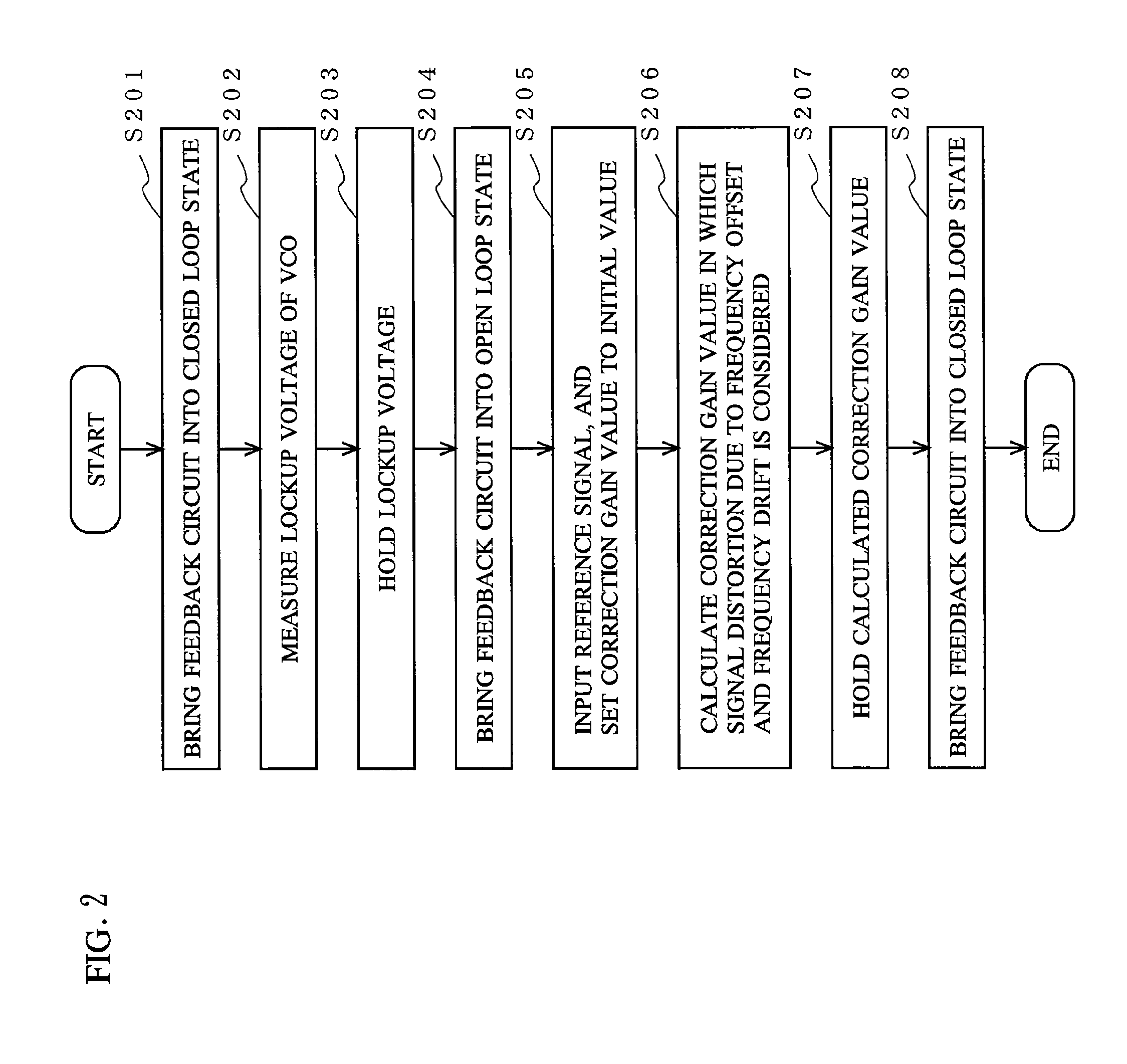
[0047]FIG. 2 is a flowchart showing a process of a first embodiment of a calibration operation performed by the two-point modulator 1 of the present invention.

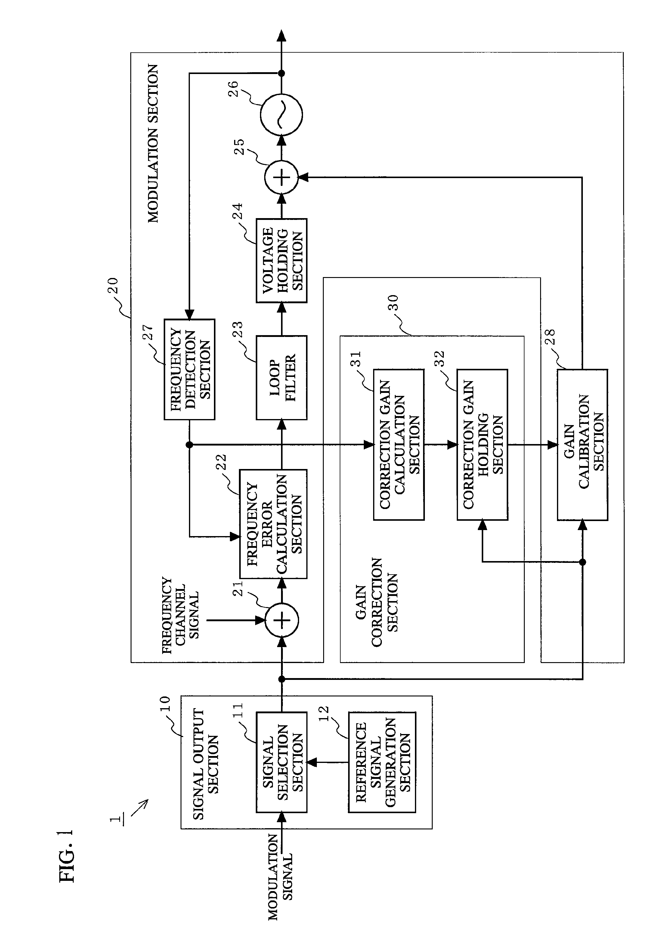
[0048]First, signal selection section 11 selects a state where neither a modulated signal nor a reference signal is inputted thereto. A frequency channel signal of a desired frequency f is inputted to the frequency error calculation section 22, the feedback circuit is brought into a closed loop state (step S201), and then a lockup voltage, which is a voltage used when the VCO 26 is locked up in a state where a non-modulated signal is used, is measured (step S202). The lockup voltage is held in the voltage holding section 24 (step S203). Thereafter, the loop filter 23 is deactivated and the lockup voltage held by the voltage holding section 24 is fixedly supplied as a voltage to be outputted to the adding section 25, thereby bringing the feedback circuit into an open loop state (step S204).

[0049]Next, after the feedback circuit...

second embodiment

[0063]A process of a second embodiment of a calibration operation performed by the two-point modulator 1 of the present invention is basically similar to the process shown in FIG. 2, except the processing of step S206. Hereinafter, the second embodiment will be described focusing on the processing of step S206.

[0064]When the gain calibration section 28 sets the correction gain value to an initial value (step S205), the reference signal generation section 12 generates a reference signal having a pulse pattern shown in FIG. 7, and outputs the generated reference signal to the correction gain holding section 32 and the gain calibration section 28. FIG. 7 is a diagram for explaining the reference signal used in the second embodiment for measuring the correction gain value of the VCO 26.

[0065]The reference signal shown in FIG. 7 includes a zero-th pulse which is a null signal representing no frequency information, a first pulse having a positive pulse value +A which represents a frequenc...

third embodiment

[0075]A process of a third embodiment of a calibration operation performed by the two-point modulator 1 of the present invention is basically similar to the process shown in FIG. 2, except the processing of step S206. Hereinafter, the third embodiment will be described focusing on the processing of step S206.

[0076]When the gain calibration section 28 sets the correction gain value to an initial value (step S205), the reference signal generation section 12 generates a reference signal having a pulse pattern shown in FIG. 10, and outputs the generated reference signal to the correction gain holding section 32 and the gain calibration section 28. FIG. 10 is a diagram for explaining the reference signal used in the third embodiment for measuring the correction gain value of the VCO 26.

[0077]The reference signal shown in FIG. 10 includes a zero-th pulse which is a null signal representing no frequency information, a first pulse having a positive pulse value +A1 which represents a frequen...


PUM


Abstract

A two-point modulator using a voltage control oscillator includes: a modulation section including a feedback circuit for performing feedback control of a signal outputted from the voltage control oscillator based on an inputted modulated signal, and a feedforward circuit for calibrating the modulated signal and outputting the calibrated modulated signal to the voltage control oscillator; a signal output section for, upon calibration processing, outputting a predetermined reference signal in place of the modulated signal, to the modulation section; and a gain correction section for, in a state where the feedback circuit is in an open loop state, calculating a frequency transition amount of the reference signal outputted from the voltage control oscillator, and correcting a gain used for calibration of the modulated signal performed by the feedforward circuit, based on the calculated frequency transition amount.

Description

BACKGROUND OF THE INVENTION[0001]1. Field of the Invention[0002]The present invention relates to a two point modulator using a voltage control oscillator and a calibration processing method, and more particularly, to a two-point modulator calibrating a gain and nonlinearity of a voltage control oscillator, and a calibration processing method performed by the two-point modulator.[0003]2. Description of the Background Art[0004]As generally known, a voltage control oscillator (hereinafter, referred to as VCO) is widely used, as a device for generating a local oscillation signal, for a modulator of a radio communication apparatus. By using the VCO, a frequency modulated signal or a phase-modulated signal can be generated. Moreover, by inputting a modulated signal having a constant envelope, generated by the VCO, to a power amplifier, and controlling a supply voltage of the power amplifier, a modulated signal having a modulated component also on its amplitude can be generated (phase shif...

Claims


Application Information

Patent Timeline
Patent Type & Authority Patents(United States)
IPC IPC(8): H03L7/06
CPCH03C3/0941H03C3/095H03C3/0966H03C3/0991
Inventor MIYANAGA, KENJIKATO, AKIRALIANG, PAUL CHENG-POBIEDKA, THOMAS
Owner PANASONIC CORP
Why Eureka
Try Eureka