Radio frequency shielded and acoustically insulated enclosure

Inactive Publication Date: 2007-07-24
IMEDCO
View PDF69 Cites 23 Cited by
  • Summary
  • Abstract
  • Description
  • Claims
  • Application Information

AI Technical Summary

Benefits of technology

[0021]It is therefore an advantage of the present invention to provide an RF shielded and acoustically insulated enclosure that efficiently employs multiple layers of insulation to absorb noise.
[0022]Another advantage of the present invention is to provide an RF shielded and acoustically insulated enclosure that absorbs the vibration and related noise generated by the MRI equipment through the supports of such equipment.
[0023]A further advantage of the present invention is to provide a self-contained RF shielded and acoustically insulated enclosure.
[

Problems solved by technology

However, as the power of MRI equipment increases, an increased amount of noise is generated due, in part, to the coil assembly of the MRI equipment.
MRI acoustic noise is mainly caused by Lorentz forces acting on the gradient coils of the MRI equipment.
As the gradient current switches direction, the gradient windings vibrate in their mountings, leading to the emission of sound waves.
MRI equipment therefore generates substantial noise, possibly at different frequencies, which travels from the MRI equipment toward the walls, floor and ceiling of the enclosure in which the MRI equipment resides.
As a result, the level of noise may at times exceed health and safety regulatory and industry standards, which seek to protect the operator of the MRI equipment (and others in the surrounding areas adjacent to such rooms or enclosures) from potentially dangerous noise levels.
Generally, adding additional layers or thickening existing layers of the insulating material in the enclosure increases the noise absorption characteristics of the enclosure.
Although the addition of the extra layers or extra thickness of the insulating materials increases

Method used


Image

  • Radio frequency shielded and acoustically insulated enclosure
  • Radio frequency shielded and acoustically insulated enclosure
  • Radio frequency shielded and acoustically insulated enclosure

Examples


Embodiment Construction

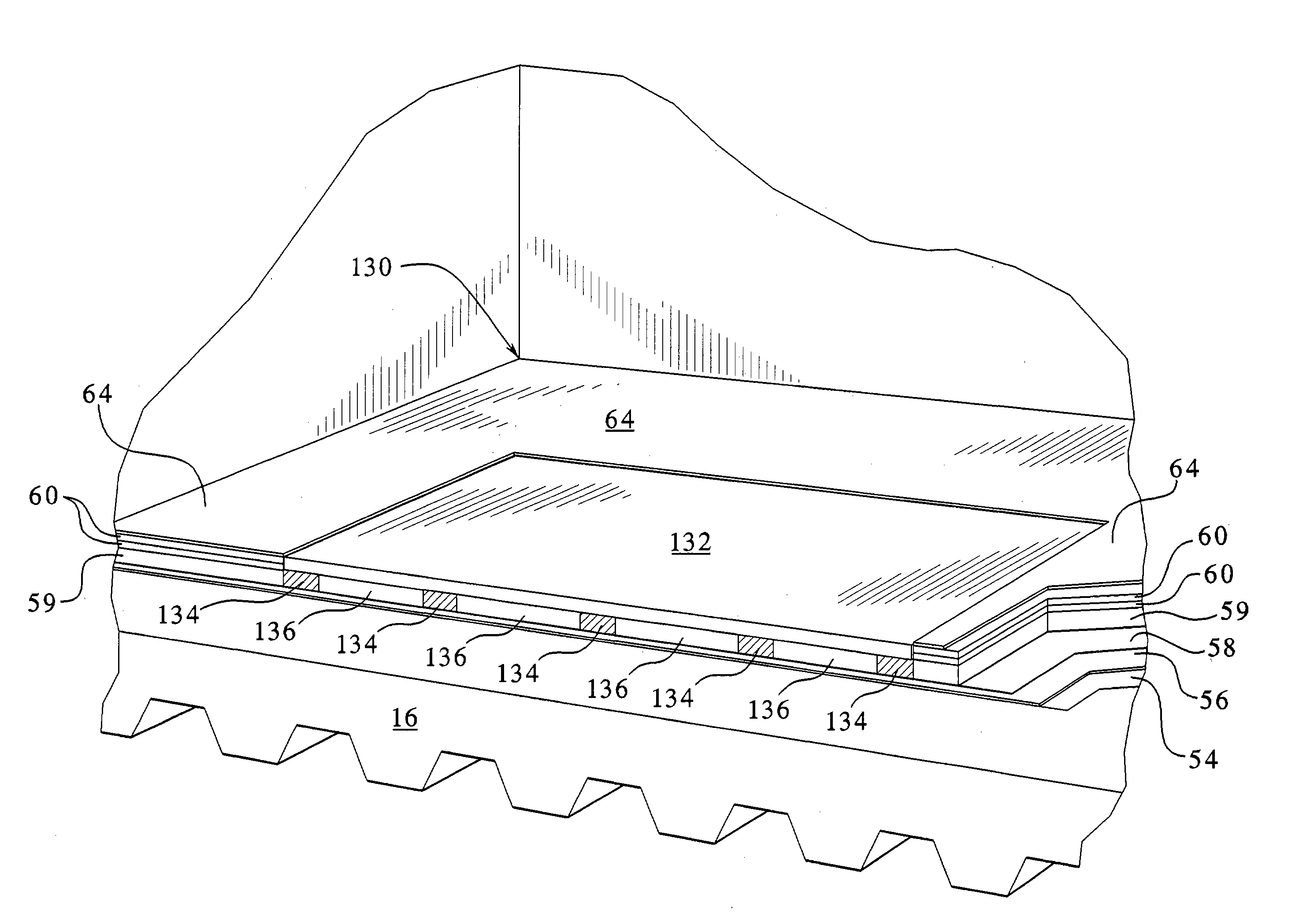
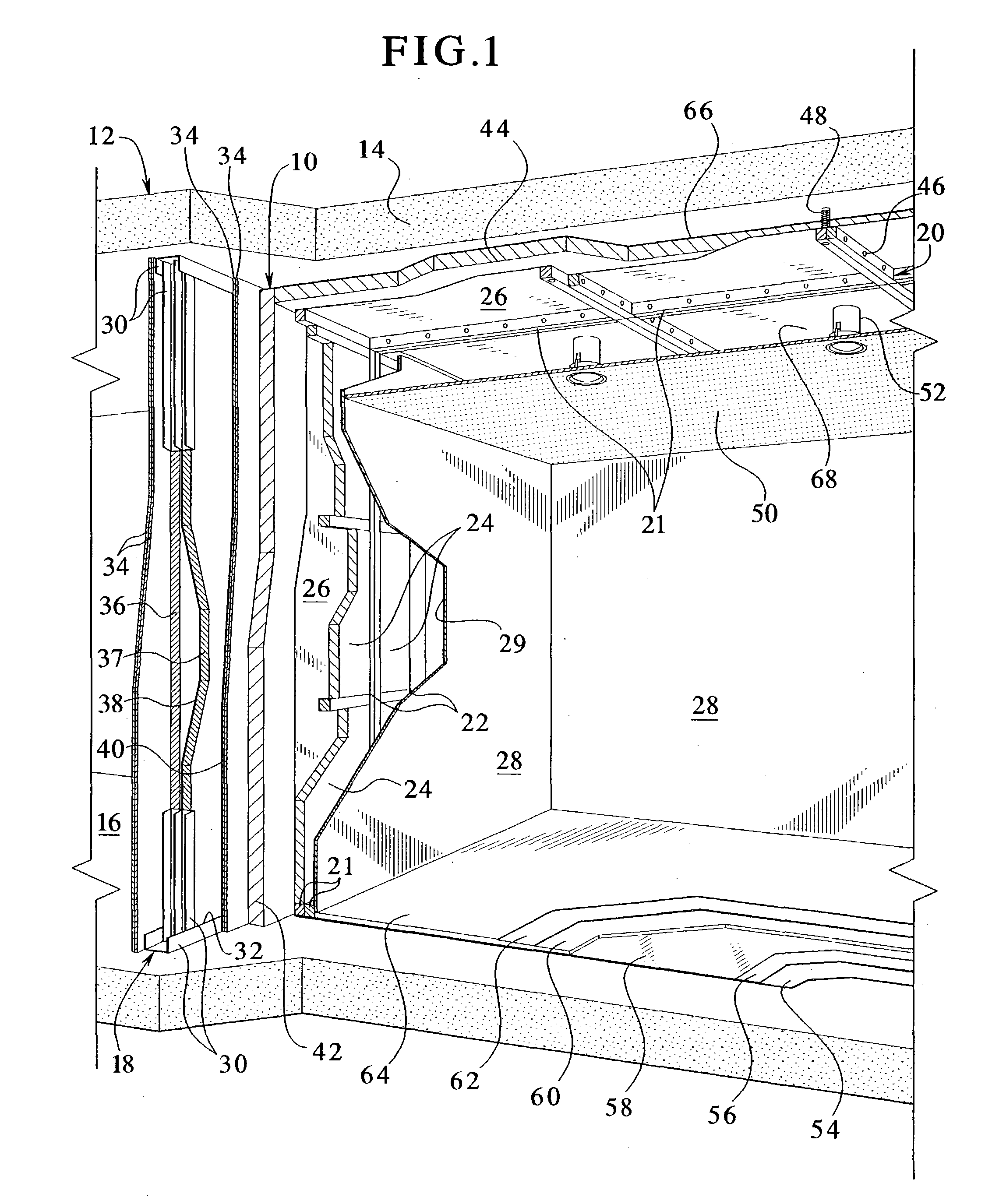
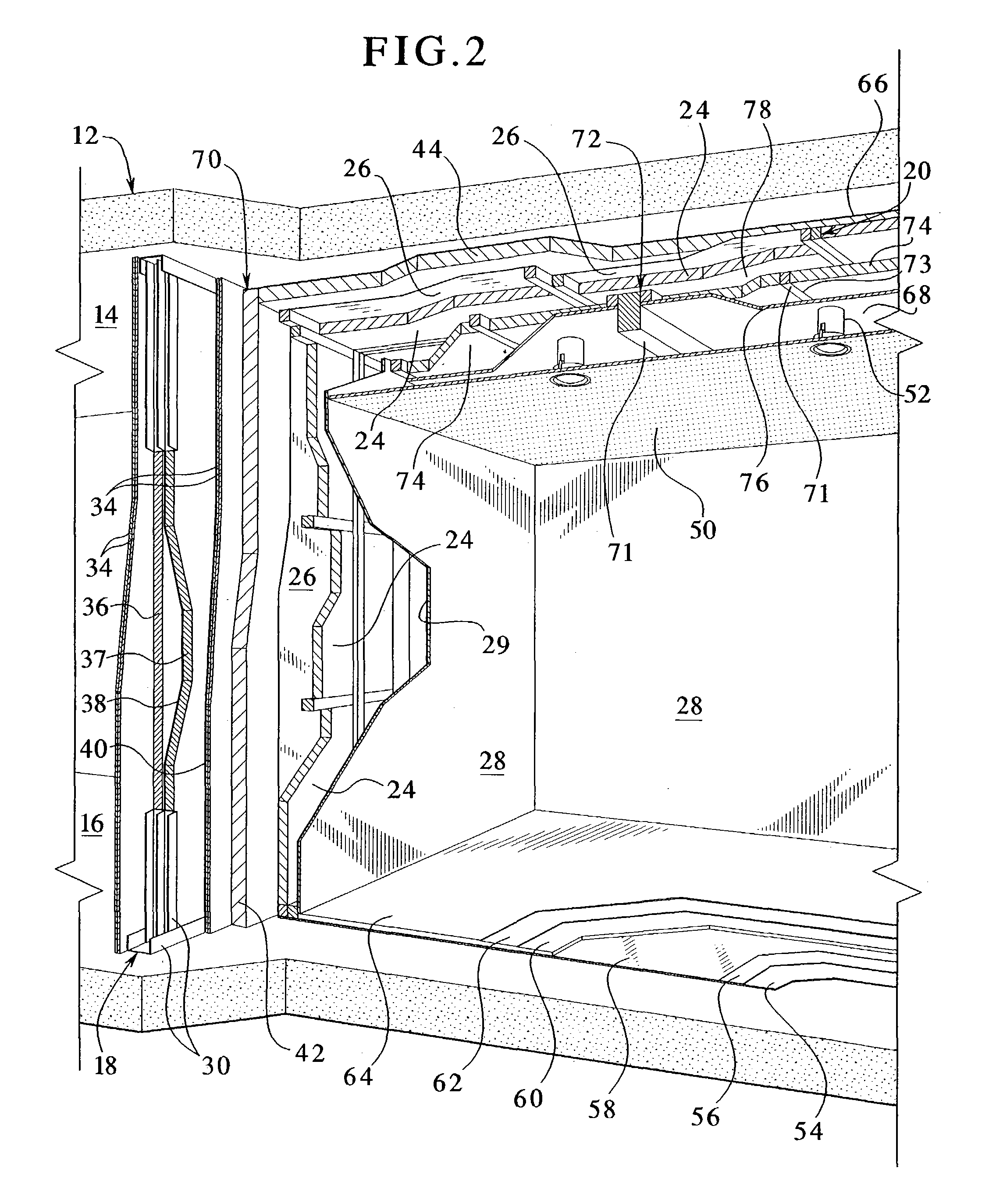
[0035]Referring now to the drawings and in particular to FIG. 1, one embodiment of the acoustically insulated and RF shielded enclosure 10 of the present invention is illustrated. The enclosure 10 resides within a building 12. The building 12 includes a ceiling 14, a floor 16 and a plurality of walls 18 connected to the floor and which support the ceiling. This embodiment of the enclosure 10 utilizes one or more of the walls 18 as an outer barrier of the enclosure, as described below.

[0036]The enclosure 10 includes a framework 20. The framework 20 in one embodiment is wooden, but may alternatively be constructed of light metal, hard plastic or any other suitable material. The framework 20 defines the top and sides of the enclosure 10. The framework 20 includes a plurality of legs or struts 21 bolted, glued or otherwise suitably fastened together. As illustrated, the framework 20 may have two or more legs side by side.

[0037]The framework 20 defines a plurality of cavities 22. The cav...


PUM


Abstract

A radio frequency (“RF”) shielded and acoustically isolated enclosure that efficiently employs multiple layers of sound insulation and absorbs airborne noise and the noise provided by magnetic resonance imaging (“MRI”) equipment through the supports of such equipment. The RF enclosure uses multiple layers and types of insulating materials positioned to maximize the noise absorption of the RF enclosure. This reduces the cost and space required by the enclosure. In one embodiment the enclosure includes a ceiling, a floor and a plurality of walls. The ceiling and walls include one or more multiple layers of different insulating materials that either abut each other or form air gaps. In one embodiment the floor includes a heavy metal plate on which the MRI equipment sits. The plate elastically couples to a conductive shield. The elastic coupling attenuates certain frequencies above the natural frequency of the metal sheet.

Description

PRIORITY CLAIMS[0001]This application is a continuation of and claims the benefit of U.S. patent application Ser. No. 10 / 000,109, filed Oct. 30, 2001 now U.S. Pat. No. 6,626,264 which is incorporated herein in its entirety.CROSS REFERENCE TO RELATED APPLICATION[0002]The application is related to the following co-pending commonly-owned patent application: “A RADIO FREQUENCY SHIELDED AND ACOUSTICALLY INSULATED DOOR,” Ser. No. 09 / 702,454, and “RADIO FREQUENCY SHIELDED AND ACOUSTICALLY INSULATED DOOR,” Ser. No. 10 / 315,471.BACKGROUND OF THE INVENTION[0003]The present invention relates in general to insulated enclosures and more particularly to radio frequency shielded and acoustically insulated enclosures.[0004]The power of magnetic resonance imaging (“MRI”) equipment is continually increasing to meet the demand in the medical community for better and faster developing images. However, as the power of MRI equipment increases, an increased amount of noise is generated due, in part, to the...

Claims


Application Information

Patent Timeline
IPC IPC(8): E04B1/00H05K9/00
CPCH05K9/0001H05K9/0003
Inventor CHRISTEN, WALTER J.
Owner IMEDCO
Why Eureka
Try Eureka