Laser annealing apparatus

a technology of annealing apparatus and laser, which is applied in the direction of manufacturing tools, transportation and packaging, nuclear engineering, etc., can solve the problems of hardly stabilizing the atmosphere, the size of the substrate, and the cost of a glass substra

Active Publication Date: 2007-07-24
AU OPTRONICS CORP
View PDF18 Cites 24 Cited by
  • Summary
  • Abstract
  • Description
  • Claims
  • Application Information

AI Technical Summary

Benefits of technology

[0010]Accordingly, one object of the present invention is to provide a laser annealing apparatus and an application of the same that can stabilize a laser-irradiated region.
[0012]A third object of this invention is to provide a laser annealing apparatus and an application of the same that can minimize any variation in the electrical properties of a polysilicon thin film transistor.
[0016]Due to the deployment of a special gas diversion nozzle in this invention, nitrogen, inert gas or some dopants infused gas may target at a laser-irradiated region with great accuracy and carry away any harmful gases produced by the laser in the stream of outflow. Therefore, this invention is particularly useful in setting up a stable environment surrounding a laser-irradiated region with a minimum gas flow and hence reduces gases charges substantially. When the apparatus according to this invention is applied to the production of polysilicon thin film transistor, possible contaminants such as the ones resulting from a reaction between liquefied silicon with moisture and oxygen in the air will no longer contaminates the polysilicon thin film transistor. Ultimately, the polysilicon thin film transistor will have electrical properties according to design.

Problems solved by technology

Yet, quartz substrate costs considerably more than a glass substrate.
Moreover, due to limitations in the size of substrate, a panel having a dimension of at most 2 to 3 inches can be produced.
Nevertheless, the aforementioned method can hardly stabilize the atmosphere around a laser-illuminated region so that all kinds of unwanted gaseous contaminants may still pollute the surrounding atmosphere during the laser annealing process.
However, because size of the chamber 104 for carrying out laser annealing process is usually large, a lot of inert gas must be used to purge the atmosphere.
Moreover, this arrangement can only produce partial improvement in the atmospheric quality.
In fact, little is done to stabilize the atmosphere close to the laser-irradiated region.

Method used


Image

  • Laser annealing apparatus
  • Laser annealing apparatus
  • Laser annealing apparatus

Examples


Embodiment Construction

[0023]Reference will now be made in detail to the present preferred embodiments of the invention, examples of which are illustrated in the accompanying drawings. Wherever possible, the same reference numbers are used in the drawings and the description to refer to the same or like parts.

[0024]Although a laser annealing apparatus is used in the embodiment of this invention, this invention can be applied to other beam-illuminating apparatus to stabilize the atmosphere surrounding a beam-illuminated region.

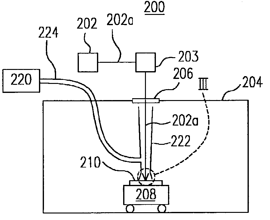
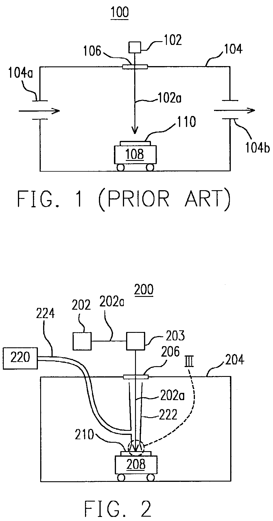
[0025]FIG. 2 is a schematic diagram of a laser annealing apparatus according to one preferred embodiment of this invention. As shown in FIG. 2, a laser annealing apparatus 200 includes a laser source 202, a gas supply device 220, a chamber 204 and a movable device 208 inside the chamber and a gas diversion nozzle 222. The laser annealing device 200 may further include an optical system 203 between the laser light source 202 and the chamber 204 for channeling a beam of laser 202a from...


PUM

PropertyMeasurementUnit
sizeaaaaaaaaaa
electron mobilityaaaaaaaaaa
brightnessaaaaaaaaaa

Abstract

An excimer laser annealing apparatus and the application of the same for stabilizing the atmosphere surrounding an area irradiated by an excimer laser. The apparatus includes a chamber, a gas diversion nozzle, an excimer laser and a gas supply device. The gas diversion nozzle is positioned inside the chamber. The laser beam produced by the excimer laser passes through the gas diversion nozzle. The gas supply device connects with the gas diversion nozzle for providing a jet of gas to the laser-irradiated area and carrying away any pollutants from the irradiated area.

Description

CROSS REFERENCE TO RELATED APPLICATIONS[0001]This application claims the priority benefit of Taiwan application serial no. 91134040, filed on Nov. 22, 2002.BACKGROUND OF INVENTION[0002]1. Field of Invention[0003]The present invention relates to a laser annealing apparatus and its applications. More particularly, the present invention relates to a laser annealing apparatus that can stabilize the surrounding atmosphere of a laser-irradiated region and the application of the same.[0004]2. Description of Related Art[0005]With the rapid development in technologies, high tech products including video, especially digital video or imaging devices has become an indispensable part in our everyday life. At present, liquid crystal display (LCD) is one of the commonest video and image display devices. In recent years, a type of thin film transistor liquid crystal display (TFT-LCD) manufactured using polysilicon fabrication technique is produced. The TFT-LCD fabricated using polysilicon has elect...

Claims


Application Information

Patent Timeline
Patent Type & Authority Patents(United States)
IPC IPC(8): B23K26/14H01L21/20C23C16/56H01L21/22H01L21/223H01L21/268
CPCC23C16/56H01L21/268H01L21/223
Inventor TSAO, YI-CHANG
Owner AU OPTRONICS CORP
Why Eureka
Try Eureka