Method and apparatus for dynamic gray level switching

a liquid crystal display and gray level technology, applied in the direction of instruments, static indicating devices, etc., can solve the problems of poor response rate, poor graphic quality, and response rate also limits the maximum switching rate between picture frames, so as to increase the response rate of gray level switching

Inactive Publication Date: 2007-07-24
HANNSTAR DISPLAY CORPORATION
View PDF7 Cites 7 Cited by
  • Summary
  • Abstract
  • Description
  • Claims
  • Application Information

AI Technical Summary

Benefits of technology

[0014]The advantage of the present invention is increased response rate of the gray level switching. Since the driving force for the current time frame is-not decided by only the current gray level but also by the previous gray level, an optimized driving force with enlarged voltage difference can be generated to increase the response rate of gray level switching.

Problems solved by technology

The smaller the difference the poorer the response rate.
This results in bad graphic quality when an LCD displays highly dynamic pictures.
Furthermore, the response rate also limits the maximum switching rate between picture frames and limits the application of an LCD for displaying TV programs.

Method used


Image

  • Method and apparatus for dynamic gray level switching
  • Method and apparatus for dynamic gray level switching
  • Method and apparatus for dynamic gray level switching

Examples


first embodiment

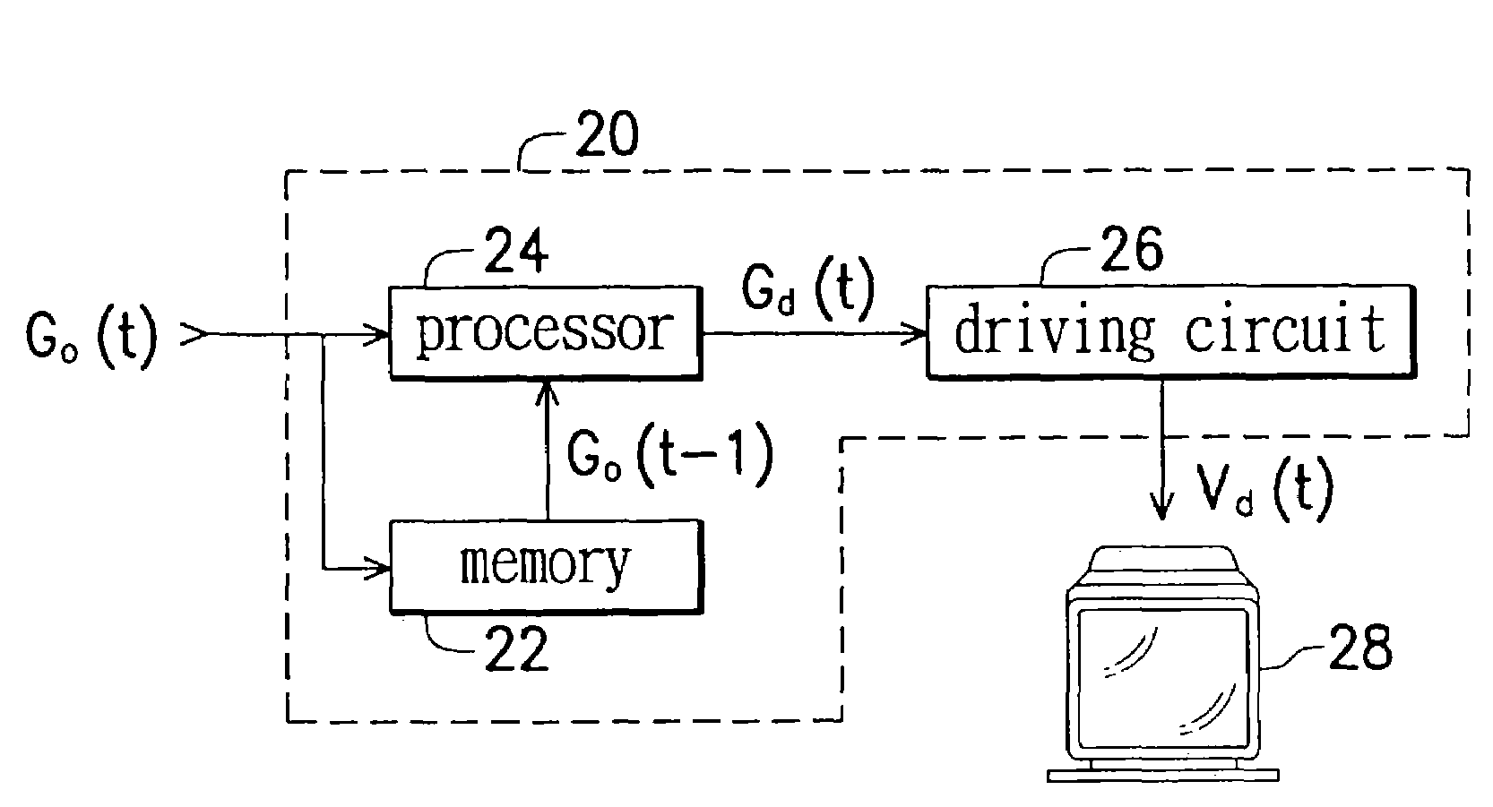
[0029]FIG. 3 illustrates a driving chip connected to an LCD. A driving chip 20 consecutively receives a current gray level Go(t) and provides an optimized driving voltage Vd(t) to drive a pixel in LCD 28, thereby making it possible for the pixel to switch its status forward to Go(t) within a single time frame. Driving chip 20 has a memory 22, a processor 24 and a driving circuit 26. Memory 22, such as a dynamic random access memory (DRAM), records a previous gray level Go(t−1), for example, the desired gray level of the previous time frame. Processor 24 generates an adjusted gray level Gd(t) according to Go(t−1) and Go(t). Driving circuit 26 receives Gd(t) and outputs a responding optimized driving force Vd(t) to drive the pixel, thus switching the transmittance of the pixel.

[0030]A look-up table 30 shown in FIG. 4 can be used to generate Vd(t). Look-up table 30 can be created by experiment or calculation. For example, if the previous gray level Go(t−1) and the current gray level Go...

second embodiment

[0041]In order to save the cost of designing and purchasing a new driving chip having the functions described in the first embodiment, the present invention can be executed by software, such as adding a function of response rate compensation for gray level switching to a video display program. FIG. 5 shows a display system according to the present invention. The video display program is stored in the memory set 40. The processor 42 executes the instructions demanded by the video display program. Once the function of the response rate compensation for gray level switching is selected, the current gray level Go(t) is consecutively transformed by processor 42 to generate the adjusted gray level Gd(t). The transformation is similar to that taught in the first embodiment. A look-up table, logic operation, or mathematical calculation can be used to generate the adjusted gray level Gd(t) with references of Go(t) and Go(t−1). FIG. 6 shows the relationship between the adjusted gray level Gd(...


PUM


Abstract

A method and apparatus for gray level dynamic switching. The method is applied to driving a display with at least one pixel. In the method of the present invention, a gray level sequence SG is provided. SG sequentially represents two or more desired gray levels Go(1), . . . , Go(T) of the pixel at consecutive time frames 1, . . . , T and comprises a current gray level Go(t) and a previous gray level Go(t−1) corresponding to time frames t and t−1, respectively. Then, the pixel is driven with an optimized driving force Vd(t) to change the pixel forward to a state corresponding to Go(t) according to Go(t) and Go(t−1). In the present invention, the optimized driving voltage Vd(t) is determined by equations of Vd(t)=Vo(t−1)+ODV and Vd(t)=a×Gd(m)3+b×Gd(m)2+c×Gd(m)+d, wherein the voltage ODV is a minimum voltage capable of obtaining one gray level transition in a determined response time.

Description

[0001]This application is a continuation-in-part of application Ser. No. 09 / 661,289 filed on Sep. 13, 2000 now abandoned, the entire contents of which are hereby incorporated by reference and for which priority is claimed under 35 U.S.C. § 120.BACKGROUND OF THE INVENTION[0002]1. Field of the Invention[0003]The present invention-generally relates to a method and apparatus for switching the gray levels of a pixel in a liquid crystal display (LCD).[0004]2. Description of the Related Art[0005]While there are-several types of liquid crystal displays (LCDs), all LCDs operate on the same general principle. A liquid crystal material is placed in a sealed but light transmissive chamber and light transmissive electrodes are placed above and below the liquid crystal material. In one type of LCD utilizing what are called twisted nematic liquid crystals, when sufficient electric potential is applied between the electrodes, the liquid crystal molecules change their alignment. The change in alignm...

Claims


Application Information

Patent Timeline
Patent Type & Authority Patents(United States)
IPC IPC(8): G09G3/36G09G3/20
CPCG09G3/3611G09G3/2011G09G2320/0252G09G2320/0261G09G2320/041G09G2340/16
Inventor CHEN, LI-YIJEN, TEAN-SEN
Owner HANNSTAR DISPLAY CORPORATION
Why Eureka
Try Eureka