Rotorcraft engine and rotor speed synchronization

Active Publication Date: 2009-09-10
KAREM AIRCRAFT INC
View PDF29 Cites 36 Cited by
  • Summary
  • Abstract
  • Description
  • Claims
  • Application Information

AI Technical Summary

Benefits of technology

[0009]The present invention provides systems, methods, and apparatus for high reliability, low weight, power transmission with shifting between multiple fixed gear ratios via synchronizing the driving and driven elements around a speed change mechanism. In preferred embodiments, the speed change mechanism is a dog c

Problems solved by technology

The reason for a variable gear ratio is that the range of output shaft speed delivered by current turboshaft engine is not sufficient to meet the speed range required by the rotors.
Turboshaft engine output speed is limited by efficiency, engine stall, and other engine operational margins.
In this

Method used


Image

  • Rotorcraft engine and rotor speed synchronization
  • Rotorcraft engine and rotor speed synchronization
  • Rotorcraft engine and rotor speed synchronization

Examples


Embodiment Construction

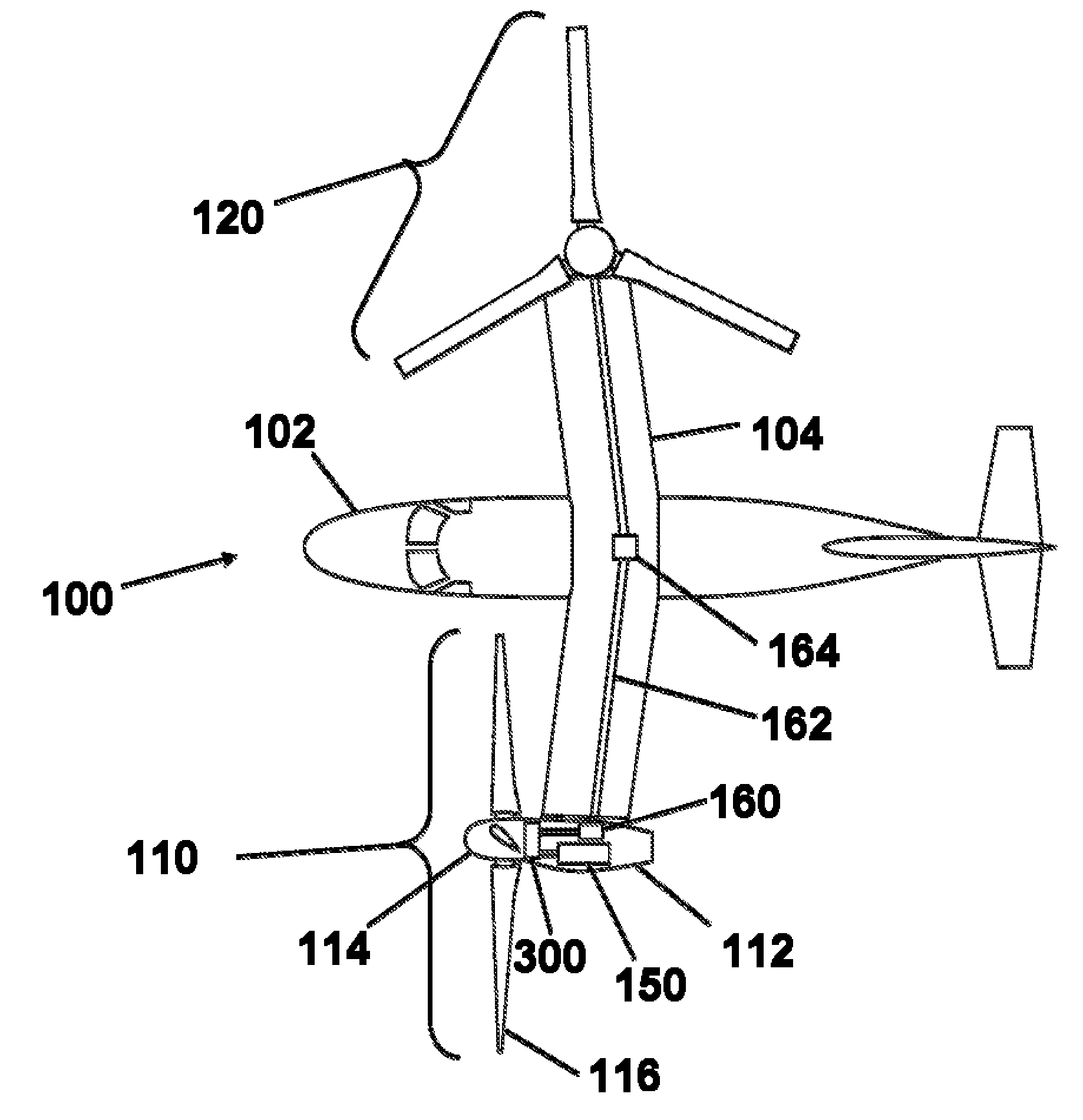
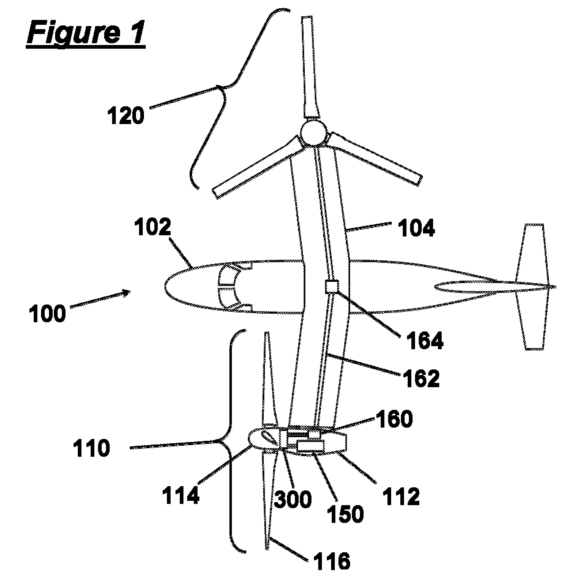
[0027]FIG. 1 is a top view schematic of a preferred tiltrotor aircraft 100. The aircraft comprises a fuselage 102, wing 104, first rotor system 110, and second rotor system 120. The second rotor system 120 is shown in a vertical orientation, consistent with helicopter-mode flight. The first rotor system 110 is shown in a horizontal orientation, consistent with airplane-mode cruise flight. In practice, the first rotor system 110 and second rotor system 120 are likely to have a substantially similar orientation at any given time in flight. A rotor system 110 comprises a hub 114 coupled to a tilting nacelle 112, which tilts with respect to the wing 104. A rotor blade 116 is coupled to the rotor hub 114. An engine 150 is preferably disposed within the tilting nacelle 112 and is coupled to a shifting gearbox 300. A miter gearbox 160 is also coupled to the shifting gearbox 300 as well as a cross-wing driveshaft 162. The cross-wing driveshaft 162 is preferably disposed within the wing 104 ...


PUM


Abstract

Systems and methods are provided in which an electrical control system independently effects acceleration of both driven and driving elements of a clutch to engage each other. In preferred embodiments the clutch is not a friction clutch, but a dog clutch, and forms part of a drive drain of a rotorcraft. A second clutch can be used, along with a mechanical interlock to prevent simultaneous engagement of the clutches. Speeds of the driven and driving elements can be sensed, and altered using at least one of a rotor, a brake, a generator, an electric motor, and a combustion motor. In rotorcraft embodiments, the gearbox can have a neutral condition in which no power is transmitted from the engine to the rotor

Description

[0001]This application claims priority to U.S. provisional application Ser. No. 61 / 034457, filed Mar. 6, 2008, the disclosure of which is incorporated herein by reference in its entirety.FILED OF THE INVENTION[0002]The field of the invention is drive trains, and especially drive trains of rotorcraft.BACKGROUND[0003]It is common practice for prior art tiltrotor aircraft to have first and second rotors, each disposed in a first and second tilting nacelle. It is further well accepted to mechanically drive the first rotor from a first engine mounted within a first tilting nacelle, and to configure the drive as a reduction gearbox driving the first rotor from the first engine. Alternative engine locations outside the nacelle have been also been proposed in the prior art.[0004]It is also common practice to mechanically connect a first rotor to the second rotor laterally across the wing of the aircraft by means of shafting, called cross-wing drive shafting. The purpose of the cross-wing dr...

Claims


Application Information

Patent Timeline
IPC IPC(8): B64D35/00
CPCB64C29/0033Y10T74/19242B64D35/00B64D31/12
Inventor WAIDE, WILLIAM MARTINKAREM, ABE
Owner KAREM AIRCRAFT INC
Why Eureka
Try Eureka