Method for determining the gain spectrum of a Raman amplifier in a WDM-transmission system

a technology of raman amplifier and gain spectrum, which is applied in the direction of electromagnetic transmission, transmission monitoring, optical resonator shape and construction, etc., can solve the problems of limited system improvement which can be obtained, degrade the signal quality, and inefficient utilization, and achieve the effect of simple adjustmen

Inactive Publication Date: 2007-07-24
XIEON NETWORKS SARL
View PDF18 Cites 2 Cited by
  • Summary
  • Abstract
  • Description
  • Claims
  • Application Information

AI Technical Summary

Benefits of technology

[0021]In principle, the use of the ASE for the EDFA fiber amplifiers would permit the gain spectrum of the distributed Raman amplifiers to be measured with absolutely no signal channels being present. For the purpose of protecting the EDFA fiber amplifiers, WDM transmission systems which have been developed to the full product stage commonly provide safeguards to prevent the EDFA fiber amplifiers being switched on when there are no channels present. Advantageously, the presence of signal channels does not disrupt the proposed method, because the ratio of the spectra at the exit from the fiber can also be determined with any arbitrary number of channels.
[0024]The accuracy of the measurement of the gain spectra in the front link sections can be increased by an artifice. When operated in regular mode, the EDFA fiber amplifier (booster) before the first link section generates comparatively little ASE, because it works with a high input level. Modem transmission systems generally provide VOAs (variable optical attenuators), adjustable attenuation elements with which the level of the individual transmitters can be balanced. These VOA attenuation elements can also be utilized to reduce the input level into the booster. With lower input levels the boosters, which are regulated to give constant output power, generate more ASE. In this way it is possible to select the ASE attributable to the booster so that it is stronger than that from the Raman amplifier.

Problems solved by technology

On the other hand, the system improvement which can be obtained is limited by the channel with the lowest gain.
The higher gain of the other channels corresponds to an inefficient utilization of the pump power deployed and, if the differences are very large, can degrade their signal quality by doubled Rayleigh backscattering.
However, the desired gain spectrum is achieved only for a quite particular distribution of the power at the individual pumping wavelengths.
In addition, when the system is installed nothing is generally known about the insertion loss between the pumping source and the actual input to the transmission fiber.
Here, the gain measurement is carried out as a function of a specific configuration of active channels, which is undesirable when the system is being commissioned.
Unfortunately this method can seldom be used in practice, because most systems are commissioned using only a very small number of channels, and only later are they upgraded.
The switching off of the Raman pumping source which this requires would disrupt the transmission of the channels which are already present.
In addition, the preparation of the source and the coupling of its output signal into the transmission system can present problems.
Since the relationship between the gain spectrum and the spectrum of the ASE is very complex for distributed Raman amplifiers, the calculation is very resource intensive and error-prone.
Since the method therefore has no knowledge of either the exact fiber characteristics or the insertion loss between the pumping source and the transmission fiber, the resulting gain spectrum can deviate significantly from that actually desired.

Method used


Image

  • Method for determining the gain spectrum of a Raman amplifier in a WDM-transmission system
  • Method for determining the gain spectrum of a Raman amplifier in a WDM-transmission system

Examples


Embodiment Construction

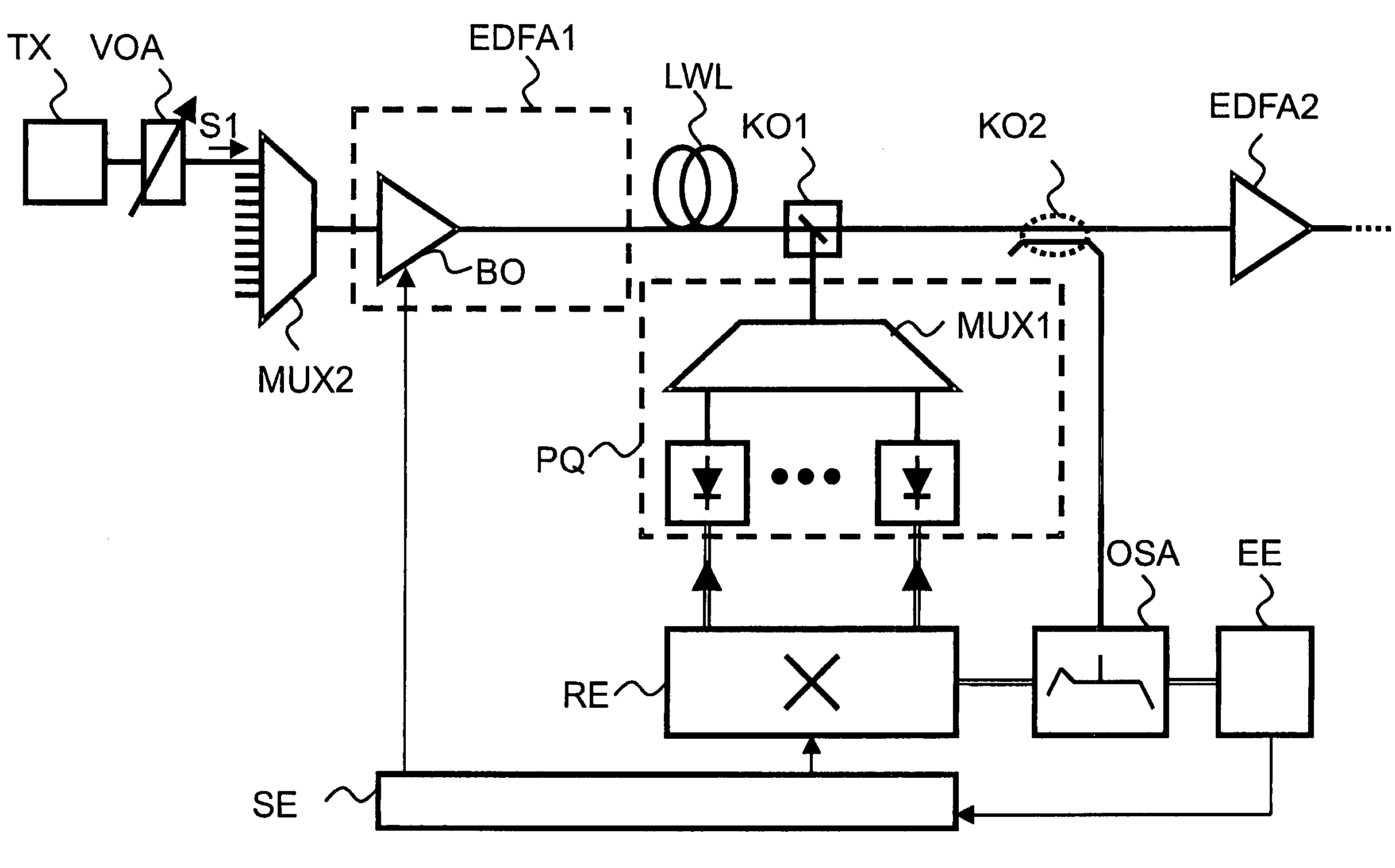
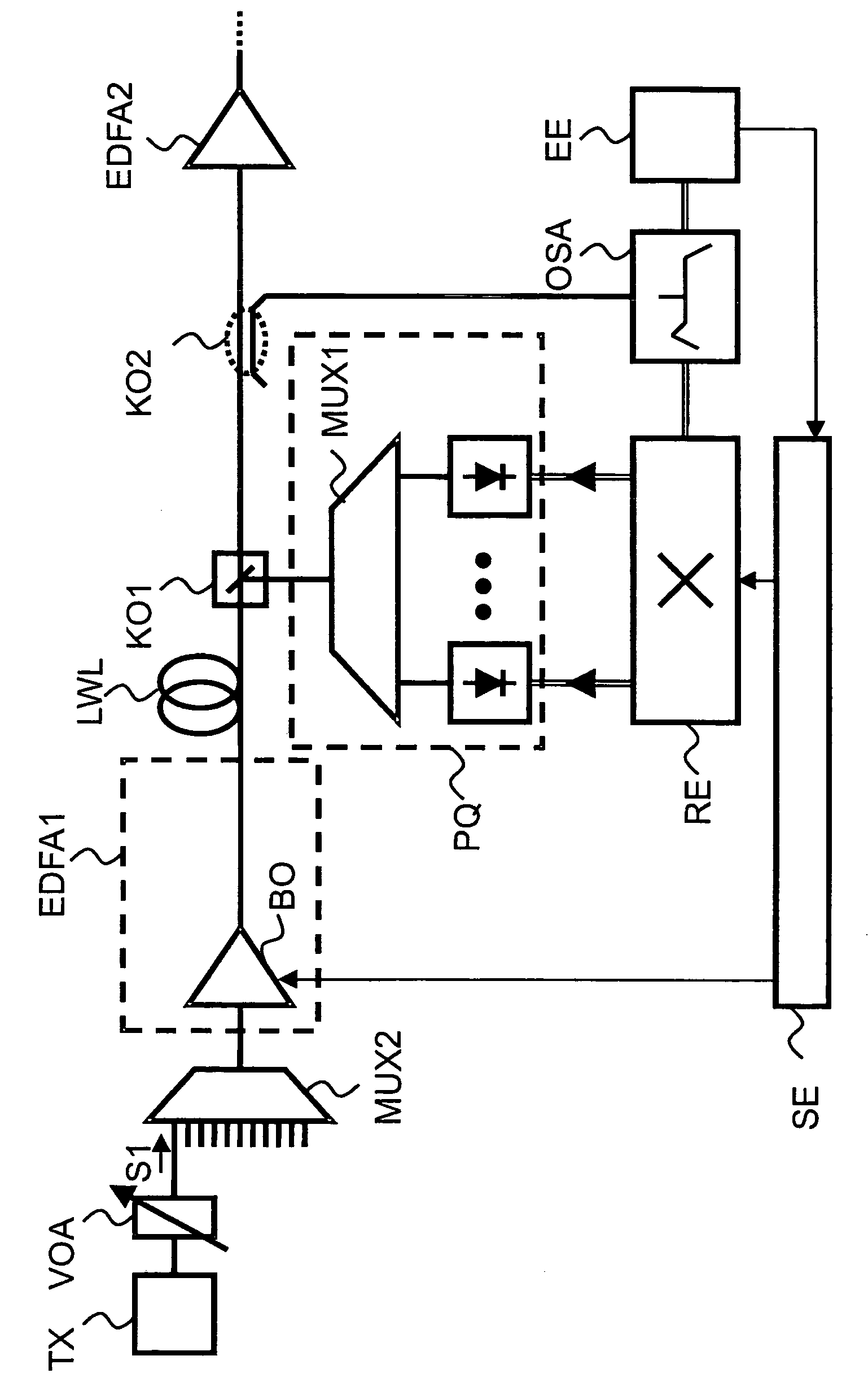
[0029]As an exemplary embodiment, consider an arrangement as shown in FIG. 1 for carrying out the method in accordance with the invention, which shows a first transmission section as a segment of a WDM transmission system. Connected to this transmission section is a Raman amplifier, which has a pumping source PQ with several pumping signals. For the purpose of generating the Raman pump radiation, the pumping source PQ at the end of the link section uses four laser diodes. Pumping signals from the pumping source PQ are combined together with the help of a wavelength-selective multiplexer MUX. The laser diodes generate signals with wavelengths of 1423 nm, 1436 nm, 1453 nm and 1467 nm. A band filter KO1 feeds the pump signals into the signal path or into an OWG transmission fiber, as applicable, in the opposite direction from the direction of propagation of the transmitted signals.

[0030]Downstream from the band filter KO1 of the pumping source PQ in the signal path is a coupler KO2. Wi...


PUM


Abstract

The invention relates to a method and device for determining the gain spectrum of a Raman amplifier having an optical amplifier, which is connected in incoming circuit thereto, in a section of a WDM transmission system. A number of spectra are recorded at the output of the Raman amplifier during which the optical amplifier or the Raman amplifier is switched on and off and a high amplified spontaneous emission is generated at the input of the Raman amplifier. Afterwards, the gain spectrum is determined on the basis of the recorded spectra.

Description

CROSS REFERENCE TO RELATED APPLICATION[0001]This application is the U.S. National Stage of International Application No. PCT / DE2003 / 002266, filed Jul. 7, 2003 and claims the benefit thereof. The International Application claims the benefits of German application No. 10239304.4 DE filed Aug. 27, 2002, both of the applications are incorporated by reference herein in their entirety.FIELD OF THE INVENTION[0002]The invention relates to a method and an arrangement for determining the gain spectrum of a Raman amplifier in accordance with the characterizing clauses of the claims.BACKGROUND OF THE INVENTION[0003]The use of distributed Raman amplification in transmission fibers permits a significant improvement in the characteristics of optical transmission systems. For example, for a given optical signal-to-noise ratio at the end of a link, the use of this technique enables the length of the individual link sections to be increased or more link sections can be bridged.[0004]When the techniqu...

Claims


Application Information

Patent Timeline
Patent Type & Authority Patents(United States)
IPC IPC(8): H01S3/00H04B10/08H01S3/08H01S3/30H04B10/073H04B10/291
CPCH04B10/0731H04B10/2916H01S3/08072H01S3/302
Inventor KRUMMRICH, PETER
Owner XIEON NETWORKS SARL
Why Eureka
Try Eureka