Hydraulic gravitational load energy recuperation

a technology of energy recuperation and gravitational load, applied in the field of hydrostatic energy conservation, can solve the problem that a large amount of the original energy used to elevate the load is lost, and achieve the effect of reducing wear and tear on the prime mover and conserving energy

Inactive Publication Date: 2007-07-31
TIMBERJACK
View PDF13 Cites 29 Cited by
  • Summary
  • Abstract
  • Description
  • Claims
  • Application Information

AI Technical Summary

Benefits of technology

[0006]The invention provides a hydraulic power system having a prime mover with a shaft that drives one or more hydraulic pumps that supply hydraulic fluid under pressure to a control valve that is operated to direct fluid from the pump to a load and to direct return fluid under pressure that is being returned from the load. Hydraulic fluid under pressure from the pump is directed in at least one position of the valve to place the return fluid into communication with a recuperation motor so as to drive the recuperation motor to turn a shaft that is mechanically connected to relieve at least part of the work required of the prime mover to drive the hydraulic system. This conserves energy that would otherwise be wasted in the pressure drop of the return fluid and reduces wear and tear on the prime mover.
[0008]In another aspect of the invention, a hydraulic system of the invention is advantageously applied to a tree feller having a felling head supported by a boom and boom control cylinders that operate to lift, lower, extend and retract the boom and having a hydraulic power system that includes a prime mover with a shaft that drives one or more hydraulic pumps to supply hydraulic fluid under pressure to a control valve that is operated to direct fluid from the pump to at least one of the boom control cylinders that is subjected to a gravitational load on the boom and to direct return fluid under pressure that is being returned from the cylinder. A recuperation valve places fluid that is compressed out of the boom control cylinder by the influence of gravity on the boom into communication with a recuperation motor that turns a shaft to relieve at least part of the work exerted by the prime mover to drive the hydraulic system.

Problems solved by technology

Thus, much of the original energy used to elevate the load is lost.

Method used


Image

  • Hydraulic gravitational load energy recuperation
  • Hydraulic gravitational load energy recuperation
  • Hydraulic gravitational load energy recuperation

Examples


Embodiment Construction

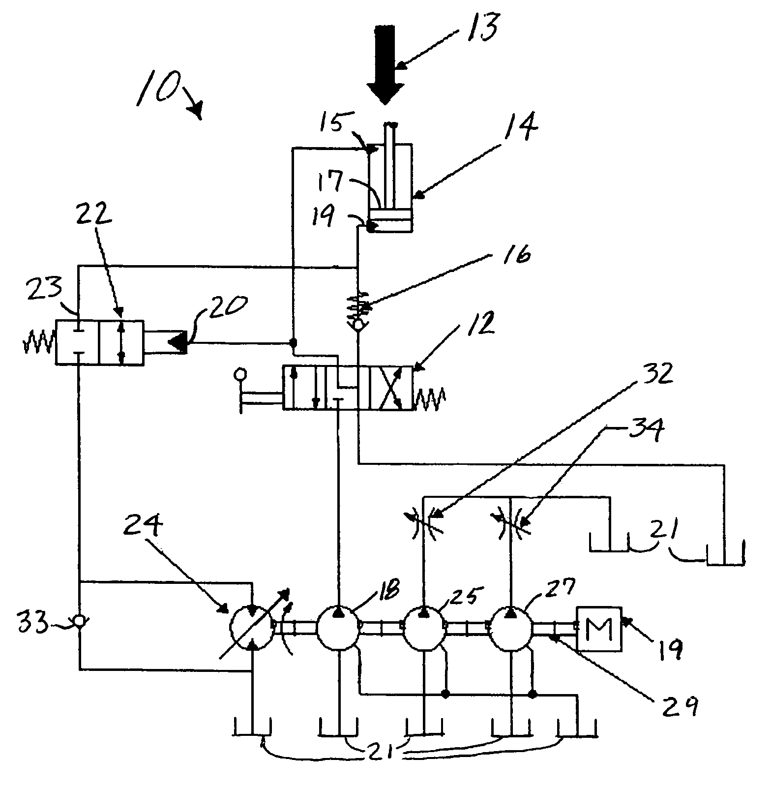
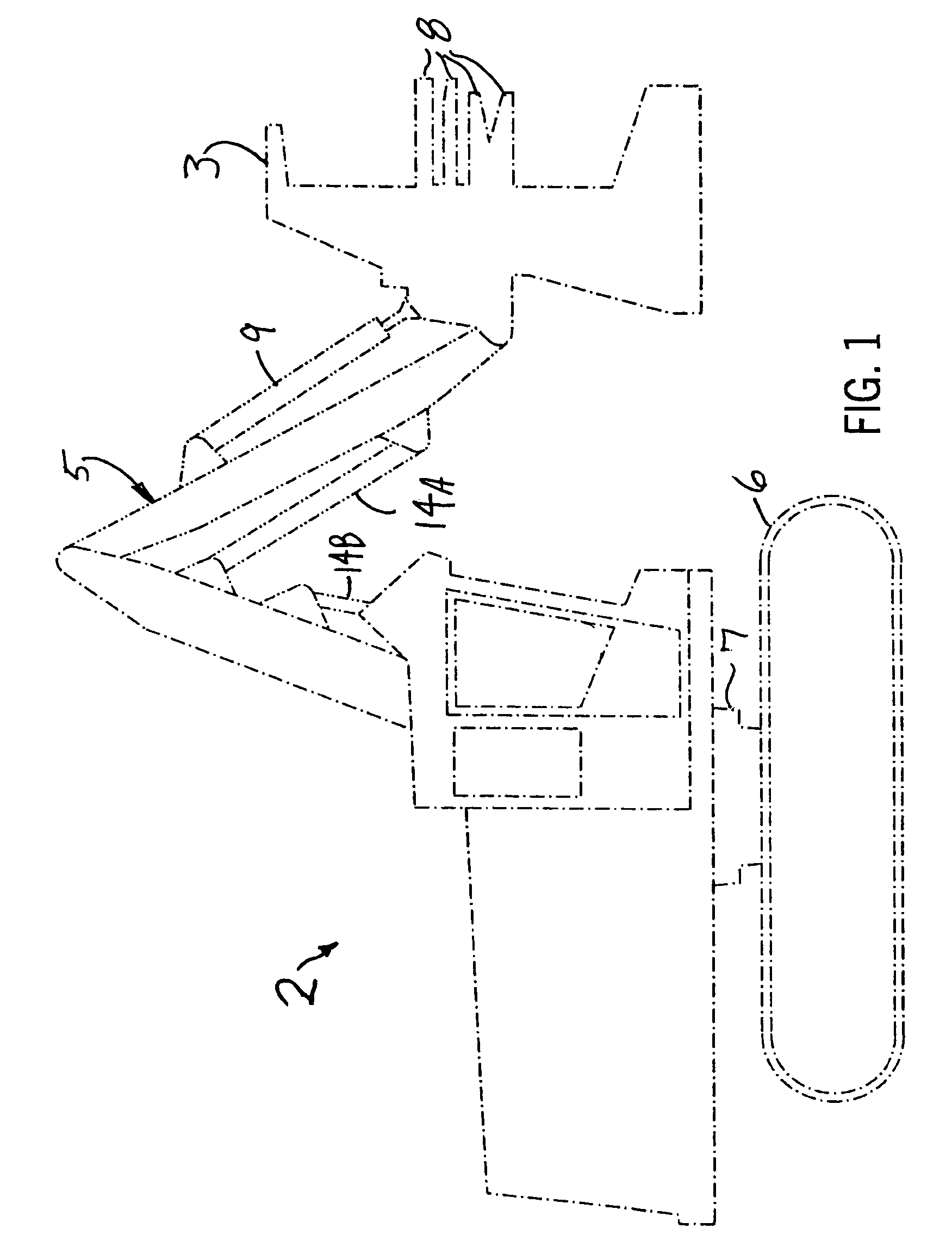
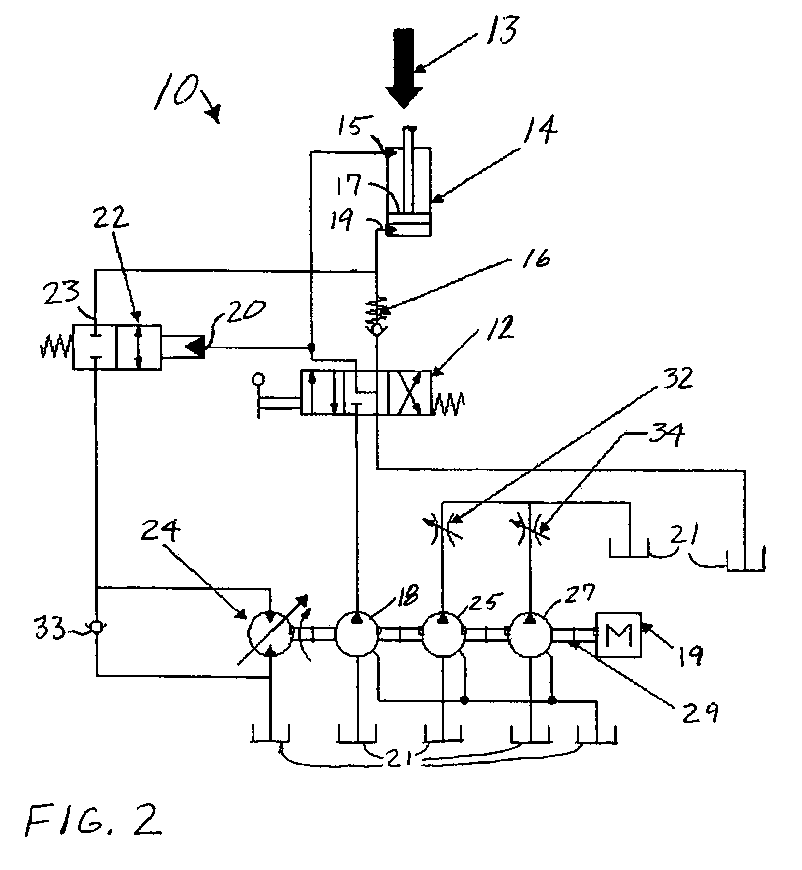
[0012]Referring to FIG. 2, in operation, a hydraulic circuit 10 has an open center directional control valve 12 that, as shown in the illustration, may be in one of three positions operated manually, although it could be electrically or hydraulically operated. The valve 12 controls the flow of fluid to and from hydraulic cylinder 14. Pressurized hydraulic fluid is supplied to the cylinder 14 from pump 18 which is driven by prime mover 19, that is, in the case of a tree feller, an internal combustion engine. The cylinder 14 may be a cylinder 14A or 14B (or both) that moves a boom 5 of a tree feller buncher as illustrated in FIG. 1, a ram or other moving part of a machine up and down, or another hydraulic device that works against gravity in one direction and with gravity in the other direction. In a tree feller buncher 2 as illustrated in FIG. 1, the saw head 3 is supported at an end of the boom 5, which is moved up and down and extended with the hydraulic cylinders 14A, 14B (more th...


PUM


Abstract

A hydraulic system has gravitional load energy recuperation by opening a recuperation piloted valve with a pilot pressure supplied by a hydraulic pump so as to drive a recuperation hydraulic motor with a source of fluid pressurized by gravity from the load. The recuperation hydraulic motor drives the mechanical drive train of the prime mover that drives the pump that supplies the load, and other pumps that supply other loads.

Description

CROSS-REFERENCE TO RELATED APPLICATION[0001]This claims the benefit of U.S. Provisional Patent Application No. 60 / 654,410 filed Feb. 18, 2005.STATEMENT CONCERNING FEDERALLY SPONSORED RESEARCH OR DEVELOPMENT[0002]Not applicable.FIELD OF THE INVENTION[0003]This invention relates to hydraulic energy conservation, and in particular to a system that uses hydraulic energy that would otherwise be wasted to supplement the power produced by a prime mover.BACKGROUND OF THE INVENTION[0004]Many types of modern hydraulic machines, including forestry machines, excavators, and material handlers, will often lift large loads and then at some later time lower them in a controlled fashion. To perform this lowering, hydraulic fluid, under pressure, will be allowed to leave the hydraulic cylinder(s) holding the load in an elevated position. This fluid will be passed through an orifice, such as a control valve, and the hydraulic pressure will be converted into heat. Thus, much of the original energy used...

Claims


Application Information

Patent Timeline
Patent Type & Authority Patents(United States)
IPC IPC(8): F15B21/14E02F9/22
CPCF15B11/003F15B21/14F16D31/02F15B2211/20523F15B2211/20538F15B2211/20576F15B2211/88
Inventor RASZGA, CALIN L.BERGQUIST, ULFGIRARD, JEFFREY R.
Owner TIMBERJACK
Why Eureka
Try Eureka