
Speed control method

a speed control and engine technology, applied in the direction of electric control, speed sensing governors, machines/engines, etc., can solve the problems of inability to rapidly change the torque of the engine, the inability to rapidly control the charge of the cylinder, and the inability to control the flow entering the manifold, etc., to achieve the effect of rapid control of the engine speed and maximize fuel economy

Inactive Publication Date: 2007-07-31
FORD GLOBAL TECH LLC
View PDF21 Cites 27 Cited by
  • Summary
  • Abstract
  • Description
  • Claims
  • Application Information

AI Technical Summary

Benefits of technology

[0007]An object of the present invention is to rapidly control engine speed to a desired engine speed while maximizing fuel economy.
[0009]By using an outlet control device that controls flow exiting the manifold (entering the cylinder), it is possible to rapidly change engine torque and engine speeds despite response delays of airflow inducted through the intake manifold. In other words, a rapid to change in cylinder charge can be achieved, thereby allowing a rapid change in cylinder air / fuel ratio while preventing disturbances in engine torque.
[0010]An advantage of the above aspect of the invention is that engine speed can be more accurately controlled to a desired engine speed without fuel economy degradation.
[0012]By changing both the inlet and outlet control devices, it is possible to rapidly change engine torque and engine speed despite response delays of airflow inducted through the intake manifold. Since the cylinder air charge can be rapidly changed, the cylinder air / fuel ratio change can be compensated and abrupt changes in engine torque can be avoided. In other words, the present invention controls manifold inlet and outlet flows in a coordinated way to allow a rapid change in engine speed regardless of manifold volume. This rapid cylinder air charge change allows torque disturbances to by rapidly rejected without using an ignition timing torque reserve.
[0014]Another advantage of the above aspect of the invention is that by using both an outlet and an inlet control device, a more controlled rapid change in engine torque and engine speed.

Problems solved by technology

In particular a disadvantage with using throttle position is that the throttle cannot quickly change engine torque since it controls flow entering an intake manifold.
Controlling flow entering the manifold cannot rapidly control cylinder charge due to manifold volume.
Another disadvantage with the known approaches is related to ignition timing.
However, when at MBT, adjustment of ignition timing in any direction decreases engine torque and fuel economy.
Therefore, when maximizing fuel economy, load torques cannot be rejected since ignition timing can only decrease engine torque.
This allows rapid engine torque control, but at the cost of degraded fuel economy.

Method used


Image

  • Speed control method
  • Speed control method
  • Speed control method

Examples


Embodiment Construction

)

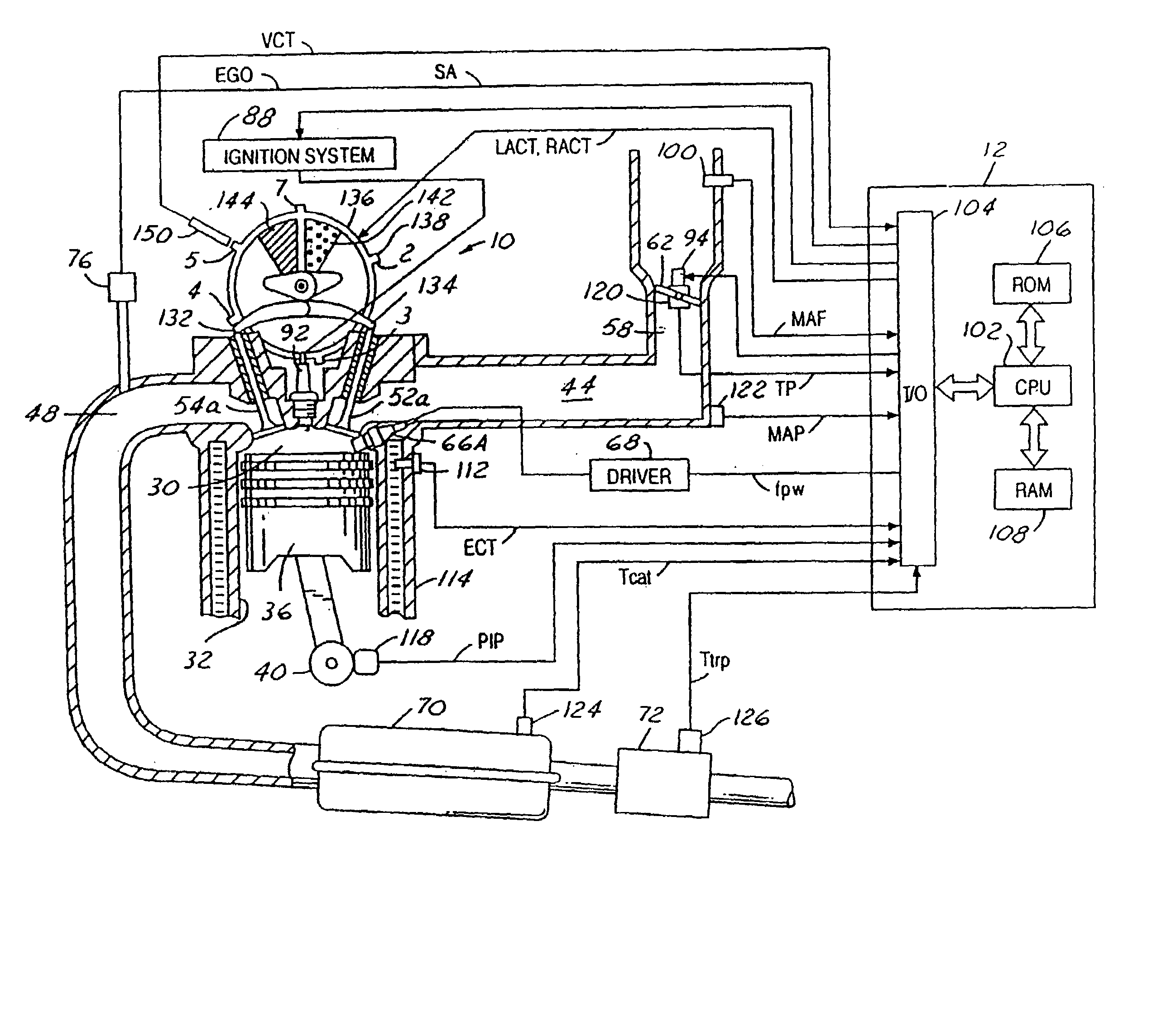
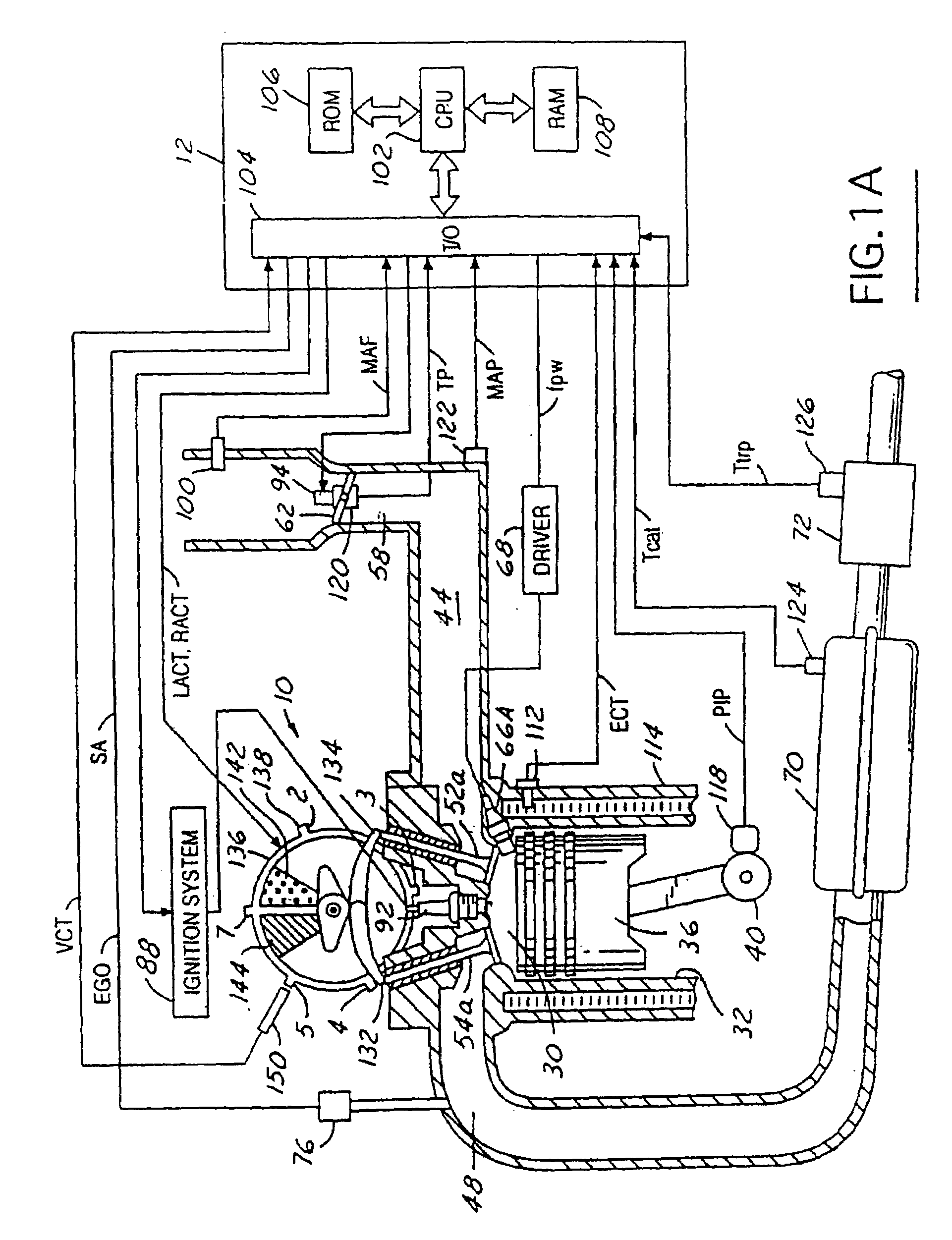
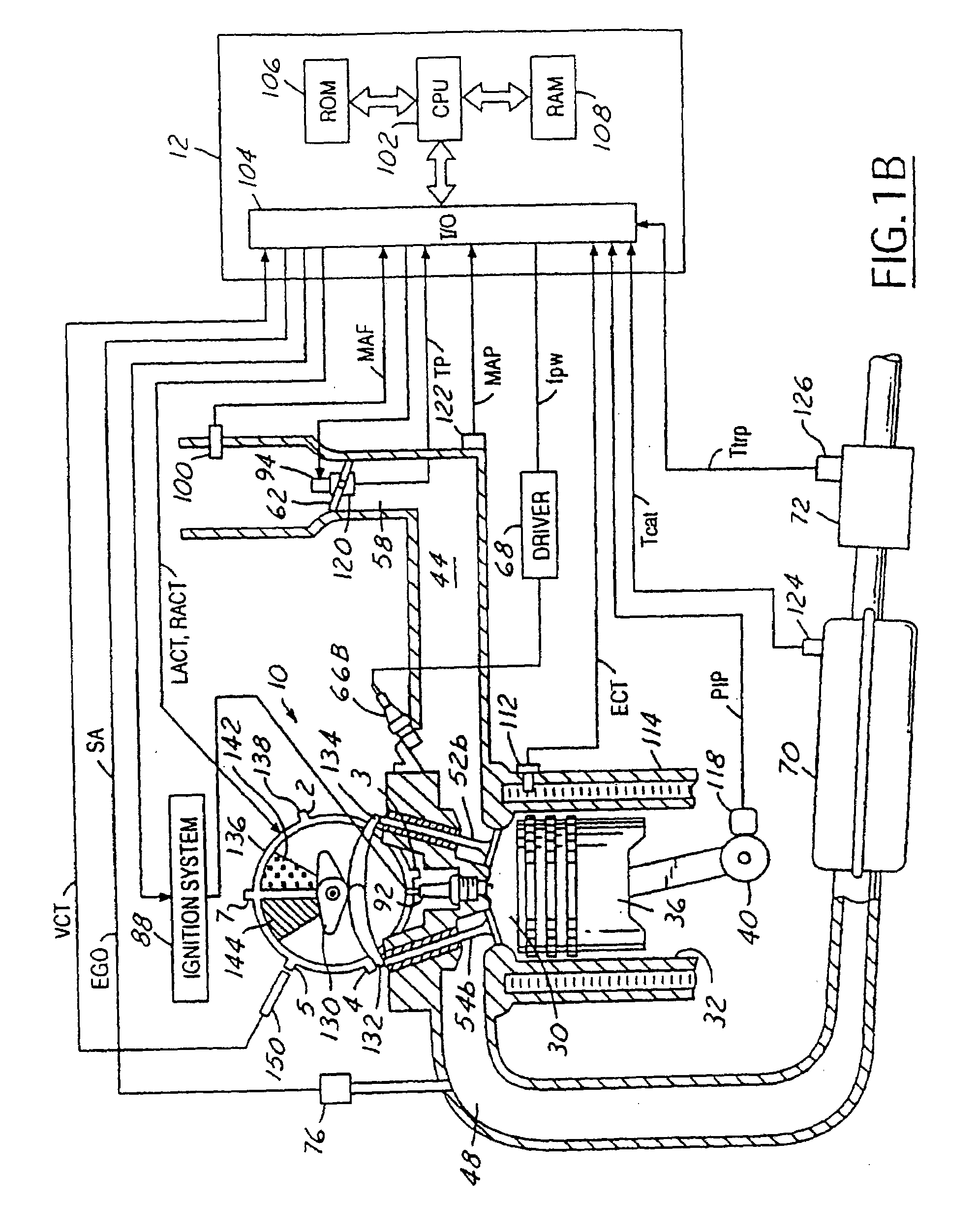
[0025]Direct injection spark ignited internal combustion engine 10, comprising a plurality of combustion chambers, is controlled by electronic engine controller 12. Combustion chamber 30 of engine 10 is shown in FIG. 1A including combustion chamber walls 32 with piston 36 positioned therein and connected to crankshaft 40. In this particular example, piston 30 includes a recess or bowl (not shown) to help in forming stratified charges of air and fuel. Combustion chamber, or cylinder, 30 is shown communicating with intake manifold 44 and exhaust manifold 48 via respective intake valves 52a and 52b (not shown), and exhaust valves 54a and 54b (not shown). Fuel injector 66A is shown directly coupled to combustion chamber 30 for delivering liquid fuel directly therein in proportion to the pulse width of signal fpw received from controller 12 via conventional electronic driver 68. Fuel is delivered to fuel injector 66A by a conventional high pressure fuel system (not shown) including a fu...


PUM


Abstract

A method for controlling an engine having both an electronically controlled inlet device, such as an electronic throttle unit, and an electronically controlled outlet device, such as a variable cam timing system is disclosed. The method of the present invention achieves cylinder air charge control that is faster than possible by using an inlet device alone. In other words, the method of the present invention controls cylinder air charge faster than manifold dynamics by coordination of the inlet and outlet device. This improved control is used to improve various engine control functions.

Description

[0001]The present application is a divisional of U.S. patent application Ser. No. 10 / 798,759, filed on Mar. 11, 2004, now U.S. Pat. No. 6,962,139 which is a divisional of U.S. patent application Ser. No. 10 / 370,025, filed on Feb. 20, 2003, now U.S. Pat. No. 6,945,225 which is a divisional of U.S. patent application Ser. No. 09 / 420,322, filed on Oct. 18, 1999 now U.S. Pat. No. 6,560,527.FIELD OF THE INVENTION[0002]The field of the invention relates to engine speed control in internal combustion engines.BACKGROUND OF THE INVENTION[0003]A vehicle's engine typically utilizes an idle speed control mode where engine speed is controlled to a desired speed when a vehicle is stationary or slowly moving and an operator is not requesting drive torque. During idle conditions, it is desirable to maintain a constant engine speed, thereby giving the operator superior drive feel. To keep engine speed constant, idle speed control should reject engine torque disturbances from various sources, such as...

Claims


Application Information

Patent Timeline
Patent Type & Authority Patents(United States)
IPC IPC(8): F02D31/00F02D9/02F01L1/34F02D13/02F02D41/00F02D41/30
CPCF01L1/34F02D13/02F02D31/002F02D41/0007F02D41/3029F02D2041/001F02D2041/002F02D2200/0402F02D2250/18Y02T10/18Y02T10/12
Inventor RUSSELL, JOHN DAVIDRUTKOWSKI, BRIAN D.
Owner FORD GLOBAL TECH LLC
Learn More