Heat dissipation device

a technology of heat dissipation device and heat generating electronic device, which is applied in the direction of indirect heat exchanger, lighting and heating apparatus, and semiconductor/solid-state device details. it can solve the problems of increasing the weight and size of the heat dissipation device, and not being able to have a sufficient heat exchange with the fins. , to achieve the effect of sufficient heat exchange, increased heat dissip

Active Publication Date: 2007-07-31
CHAMP TECH OPTICAL FOSHAN
View PDF10 Cites 22 Cited by
  • Summary
  • Abstract
  • Description
  • Claims
  • Application Information

AI Technical Summary

Benefits of technology

[0007]According to a preferred embodiment of the present invention, a heat dissipation device comprises a fin unit and at least a heat pipe. The heat pipe comprises an evaporating section and a condensing section extending through the fin unit. The fin unit comprises a plurality of fins stacked together. Each fin comprises two planar sections and a wavy section between the two planar sections. Two V-shaped sections extend laterally outwardly from the planar sections, respectively. By the wavy section and the V-shaped sections, the fins of the fin unit can have an increased heat dissipation area and enhanced strength. Furthermore, the wavy sections and the V-shaped sections of the fins can prevent an airflow through the fin units to escaped from the fin unit from lateral sides thereof. Thus, the fin unit can have a sufficient heat exchange with the airflow to thereby effectively dissipate the heat of the fin unit absorbed from a heat generating device to surrounding environment.

Problems solved by technology

However, this way will increase the weight of the heat dissipation device, which is disadvantageous in view of lightweight requirement of electronic products.
This way will increase both the weight and size of the heat dissipation device, which is disadvantageous in view of compact requirement of the electronic products.
This causes the airflow not able to have a sufficient heat exchange with the fins.
Therefore, the airflow cannot be sufficiently utilized to dissipate heat absorbed by the fin unit from the heat-generating electronic device.
Accordingly, heat dissipation effectiveness of the conventional heat dissipation device 1 is not totally satisfied.
Finally, the planar configuration of the fins makes the fins too weak to withstand an impact force acting on the fins by the airflow.
The airflow can cause the fins to vibrate and generate noise.

Method used


Image

  • Heat dissipation device
  • Heat dissipation device
  • Heat dissipation device

Examples


Embodiment Construction

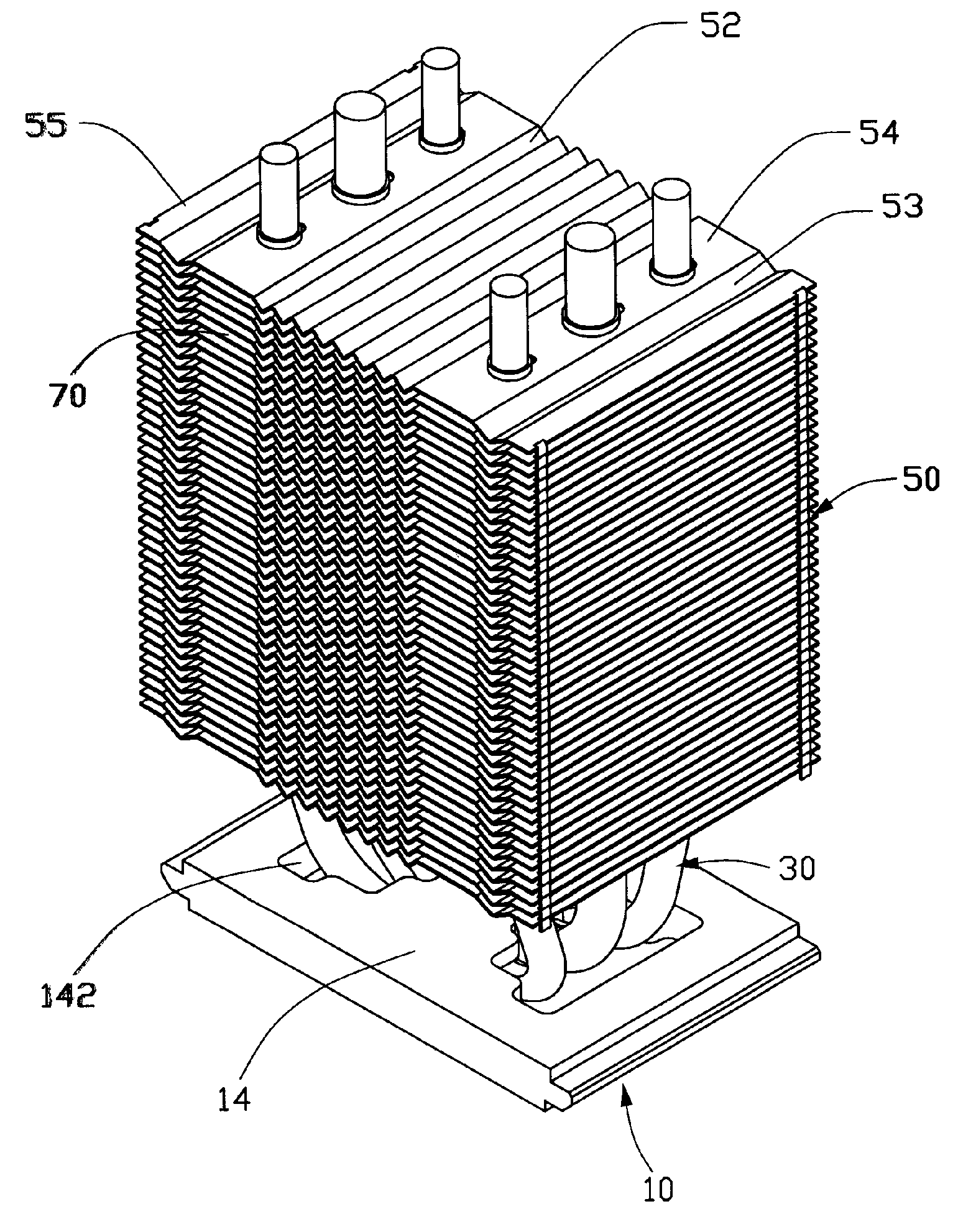
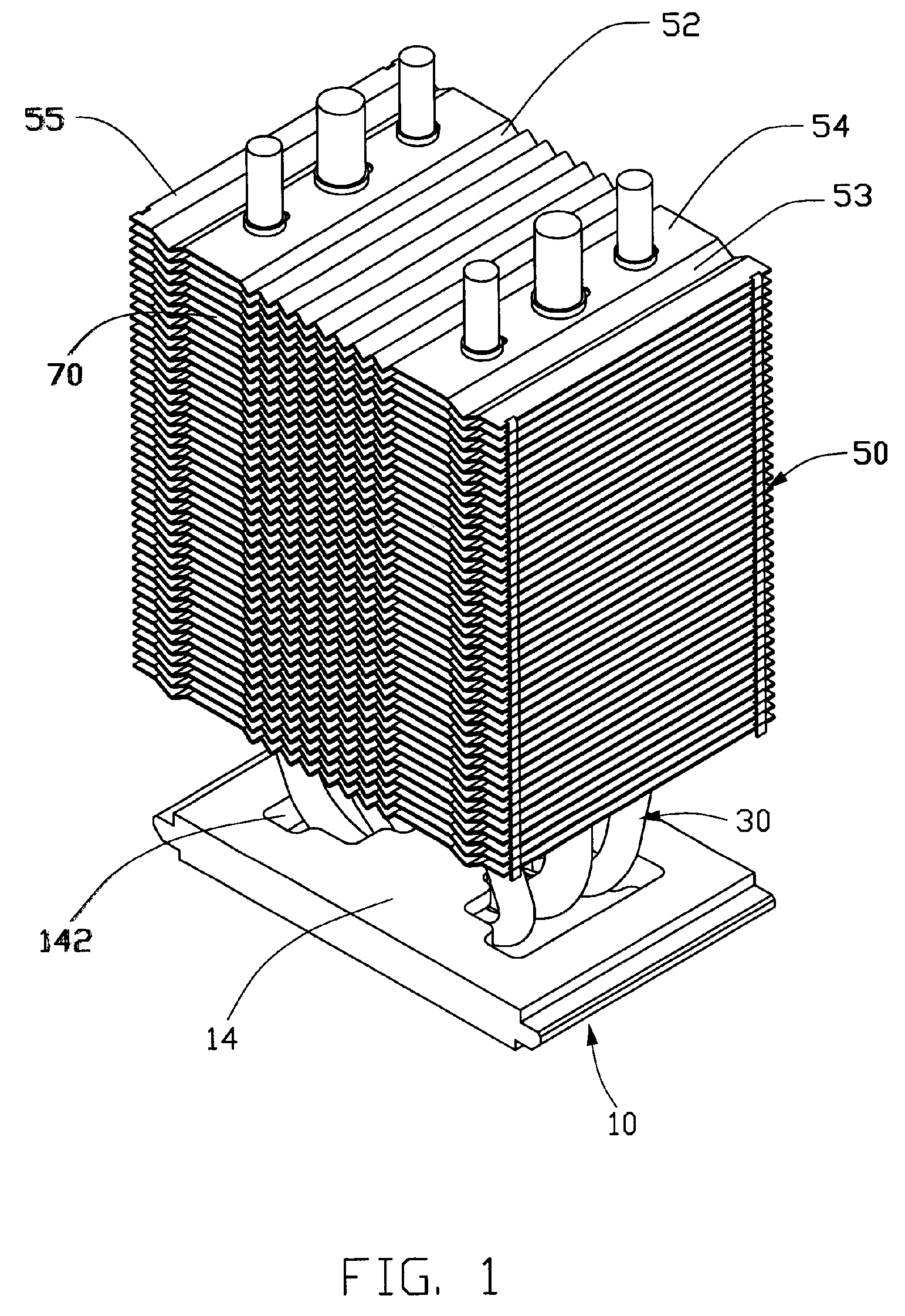
[0015]Referring to FIGS. 1-2, a heat dissipation device according to a preferred embodiment of the present invention comprises a base 10, a fin unit 50, and three heat pipes 30 connecting the base 10 and the fin unit 50.

[0016]The base 10 is rectangle-shaped and comprises a bottom wall 12 and a cover 14 mounted on the bottom wall 12. A space is defined between the bottom wall 12 and the cover 14.

[0017]Referring to FIG. 3, the bottom wall 12 is made of a flat metal plate (for example, a copper plate) and has a bottom surface 122 for thermally contacting with a heat generating device, such as a CPU (not shown). Four circular holes 120 are respectively defined in four corners of the bottom wall 12. The cover 14 comprises four poles 140 extending downwardly from a bottom side thereof corresponding to the circular holes 120 of the bottom wall 12. A concave 144 is defined in a lower portion of the cover 14. A pair of openings 142 is defined through the cover 14 near two opposite lateral si...


PUM


Abstract

A heat dissipation device includes a fin unit (50), and at least a heat pipe (30) including an evaporating section (32) and at least a condensing section (34) extending through the fin unit. The fin unit includes a plurality of fins stacked together. Each fin comprises a wavy and a V-shaped section (52,53) and a planar section (54) therebetween. The wavy and V-shaped sections of the fins can guide an airflow flowing into the fin unit to smoothly flow therethrough, and prevent escape of the airflow from lateral directions of the fin unit. Furthermore, the wavy and V-shaped sections increase the heat dissipation area of the fins and strengthen the fins.

Description

FIELD OF THE INVENTION [0001]The present invention relates generally to a heat dissipation device, and particularly to a heat dissipation device for a heat generating electronic device.DESCRIPTION OF RELATED ART [0002]As computer technology continues to advance, electronic components such as central processing units (CPUs) of computers are being made to provide faster operational speeds and greater functional capabilities. When a CPU operates at high speed in a computer enclosure, its temperature can increase greatly. It is desirable to dissipate the generated heat quickly; thus, a heat dissipation device is often attached on the CPU to efficiently remove the heat generated thereby.[0003]FIG. 6 shows a conventional heat dissipation device 1. The heat dissipation device 1 comprises a fin unit 2, a heat pipe 4 extending through the fin unit 2, and a cooling fan (not shown) for generating an airflow. The fin unit 2 includes a plurality of fins stacked together. Each fin is planar and p...

Claims


Application Information

Patent Timeline
Patent Type & Authority Patents(United States)
IPC IPC(8): F28F1/22F28D15/02
CPCF28D15/0266F28F1/32H01L23/3672H01L23/427F28D15/0275H01L23/467H01L2924/0002H01L2924/00F28F2215/10
Inventor HAO, MING-LIANGLIN, YEU-LIHHUANG, AI-MINYANG, MING
Owner CHAMP TECH OPTICAL FOSHAN
Why Eureka
Try Eureka