
Image recording apparatus and head driving control apparatus

a technology of image recording and control apparatus, which is applied in the direction of printing, other printing apparatus, etc., can solve the problems of reducing the reliability of the piezoelectric element, the reliability of the head, and the inability to optimize the driving signal for the small, so as to improve the reliability of the droplet discharging head.

Inactive Publication Date: 2007-07-31
RICOH KK
View PDF44 Cites 17 Cited by
  • Summary
  • Abstract
  • Description
  • Claims
  • Application Information

AI Technical Summary

Benefits of technology

[0015]It is a first object of the present invention to provide a head driving control apparatus and an image recording apparatus for improving reliability of a droplet discharging head such as an inkjet head in the image recording apparatus.
[0021]a third waveform element for expanding the volume of the pressurizing chamber from the contracted state;
[0024]According to this invention, the driving voltage can be applied only when printing is performed. Thus, the time for applying voltage on the pressure generation part can be shortened, so that reliability increases.
[0032]In this invention, the pulse width of the second waveform element may be determined such that droplet discharge speed is maximized. According to this invention, the image recording apparatus can make the most of pressure vibration in the pressurizing chamber caused by applying the first waveform element, so that an optimized small droplet can be obtained and the voltage of the third waveform element can be lowered.
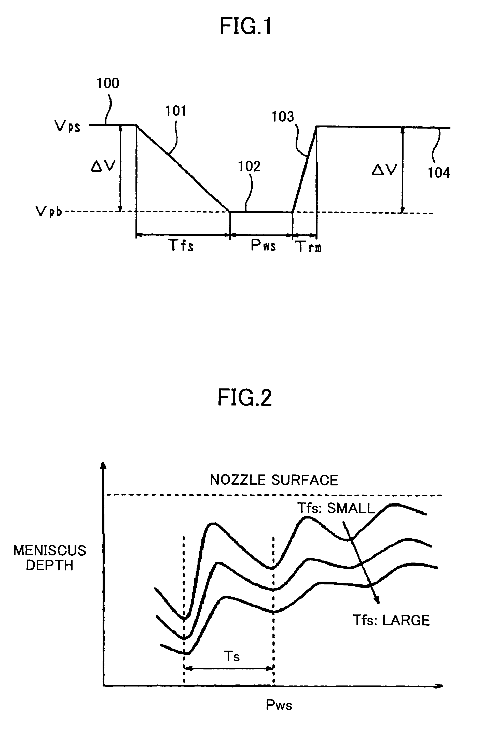
[0040]According to this invention, the first waveform element enables slowing the speed of expanding the volume of the pressurizing chamber, so that the pressure in the fluid supply chamber (ink supply chamber) can be decreased and ink supply from the fluid supply chamber can be slowed. As a result, the meniscus can be pulled by using the first waveform element. Then, the second signal enables increasing the speed of expanding the volume of the pressurizing chamber to increase the pressure in the fluid supply chamber. As a result, voltage used for discharging ink can be decreased. Thus, a small droplet can be obtained while enough droplet discharge speed is kept.

Problems solved by technology

However, in the conventional “pull and shoot” method by using the above-mentioned piezoelectric element (piezoelectric vibrator) of d33 deformation, there is a problem in that the voltage is always applied to the piezoelectric element even when printing is not performed, so that reliability of the piezoelectric element, and by extension, reliability of the head, decreases.
However, there is a problem in that it is difficult to optimize the driving signal for the small dot only by setting the potential difference ΔV1 of the driving signal to be greater than the potential difference ΔV2 of the driving signal.
Therefore, pulled depth of the nozzle meniscus cannot be large.
On the other hand, if the volume expanding speed of the ink pressure chamber is decreased, pressure in the ink supply chamber cannot be increased.
Thus, it cannot be expected to realize efficient ink discharge by using the pressure in the ink supply chamber.
That is, when it is intended to obtain a small ink droplet by using a large meniscus depth, desired ink discharge speed cannot be obtained.
Thus, a large discharge voltage is necessary.
However, when ink discharge speed is increased by using a large discharge voltage, the ink discharge amount becomes large at the same time.
Thus, the desired size of a small ink droplet cannot be obtained.
However, the ink discharge speed becomes slow.

Method used


Image

  • Image recording apparatus and head driving control apparatus
  • Image recording apparatus and head driving control apparatus
  • Image recording apparatus and head driving control apparatus

Examples


second embodiment

[0114]Next, the head driving control apparatus of the present invention will be described with reference to FIG. 11. In this embodiment, a large ink droplet is discharged by applying a plurality of driving pulses continuously in one driving period, wherein each driving pulse is a so-called “push and shoot” pulse for discharging an ink droplet by contracting the volume of the pressurizing chamber.

[0115]In this embodiment, the driving waveform generation circuit 77 generates and outputs a driving waveform Pv including a plurality of driving pulses shown in FIG. 11(a), and this driving waveform Pv is applied to the piezoelectric vibrator 52 that is a pressure generation part via the switch circuit 84. That is, the driving waveform Pv is formed by time-series four pulses Pa and Pb each used for discharging an ink droplet by contracting the volume of the pressurizing chamber in a driving period. Difference between the driving pulse Pa and the driving pulse Pb is only the falling time con...

third embodiment

[0120]Next, the head driving control apparatus of the present invention will be described with reference to FIG. 12. Also in this embodiment, a plurality of driving pulses are applied to form a large ink droplet.

[0121]In this embodiment, as shown in FIG. 12(a), each pulse width Pw2, Pw3 of second and third driving pulses Pa2, Pa3 is larger than the pulse width Pw1 of the first driving pulse Pa1 (Pw123). That is, the sum of the parameters for the driving pulse Pal is twice as large as Ts (n=2, Ts×2), the sum for the driving pulse Pa2 is three times as large as Ts (n=3, Ts×3), and the sum for the driving pulse Pa3 is four times as large as Ts (n=4, Ts×4).

[0122]Since the pressure in the pressurizing chamber increases as the driving pulse is applied repeatedly, pressure change becomes large if the same driving pulse is applied continuously. Therefore, there is a possibility that discharge cannot be performed since bubbles are involved when the volume of the pressurizing chamber is expan...

fourth embodiment

[0129]Next, the head driving control apparatus of the present invention will be described with reference to FIGS. 15(a)-15(e). In this embodiment, a plurality of driving pulses are generated, and a desired waveform is obtained from the plurality of driving pulses. In this embodiment, the driving waveform generation circuit 77 generates and outputs six driving pulses (first to sixth pulses P1-P6) in one driving period as the driving waveform Pv.

[0130]In the first pulse P1, the waveform parameters are set such that the volume of the pressurizing chamber 46 is contracted, but the ink droplet is not discharged (for example, the rising time constant tr is set to be large). The first pulse P1 becomes a fourth driving signal Pvd for contracting the volume of the pressurizing chamber without discharging any ink droplet.

[0131]In each of the second to fifth pulses P2-P5, the waveform parameters are set such that the volume of the pressurizing chamber 46 is contracted so as to discharge an ink...


PUM


Abstract

A head driving control apparatus for driving a pressure generation part in a droplet discharging head outputs a driving signal including: a first waveform element for contracting the volume of a pressurizing chamber without discharging a droplet; a second waveform element for keeping a contracted state until a meniscus in a nozzle moves toward the pressurizing chamber; a third waveform element for expanding the volume of the pressurizing chamber from the contracted state; a fourth waveform element for keeping an expanded state; and a fifth waveform element for contracting the volume of the pressurizing chamber to discharge a droplet.

Description

TECHNICAL FIELD[0001]The present invention relates to an image recording apparatus such as an inkjet printer, and a head driving control apparatus for the image recording apparatus.BACKGROUND ART[0002]An inkjet recording apparatus used as an image recording apparatus (an image forming apparatus) such as a printer, a facsimile, a copier, a plotter and the like is provided with an inkjet head as a droplet discharging head. The inkjet head includes nozzles for discharging ink droplets, ink channels (the ink channel may be called a discharge chamber, a pressure chamber, a pressurizing fluid chamber, a fluid chamber, a pressurizing chamber or the like) each of which is connected to the nozzles, and pressure generation parts for pressurizing ink in the ink channels. Although there are various kinds of droplet discharging heads such as for discharging fluid resists as droplets, or for discharging a sample of DNA as droplets, for example, the inkjet head will be mainly described as in the f...

Claims


Application Information

Patent Timeline
Patent Type & Authority Patents(United States)
IPC IPC(8): B41J29/38B41J2/045
CPCB41J2/04553B41J2/04581B41J2/04588B41J2/04593B41J2/04595B41J2/04596B41J2002/14411
Inventor KUSUNOKI, MASANORISHINGYOHUCHI, MITSURU
Owner RICOH KK
Learn More