
Mass spectrometer with an ion trap

a mass spectrometer and ion trap technology, which is applied in the direction of mass spectrometers, instruments, separation processes, etc., can solve the problems of deteriorating the mass resolution of the mass spectrometer, difficult determination of the exact mass to charge ratio, etc., to reduce the variation in the starting point of ions, improve the accuracy of mass analysis, and reduce the effect of flight time errors

Active Publication Date: 2007-07-31
SHIMADZU CORP
View PDF14 Cites 14 Cited by
  • Summary
  • Abstract
  • Description
  • Claims
  • Application Information

AI Technical Summary

Benefits of technology

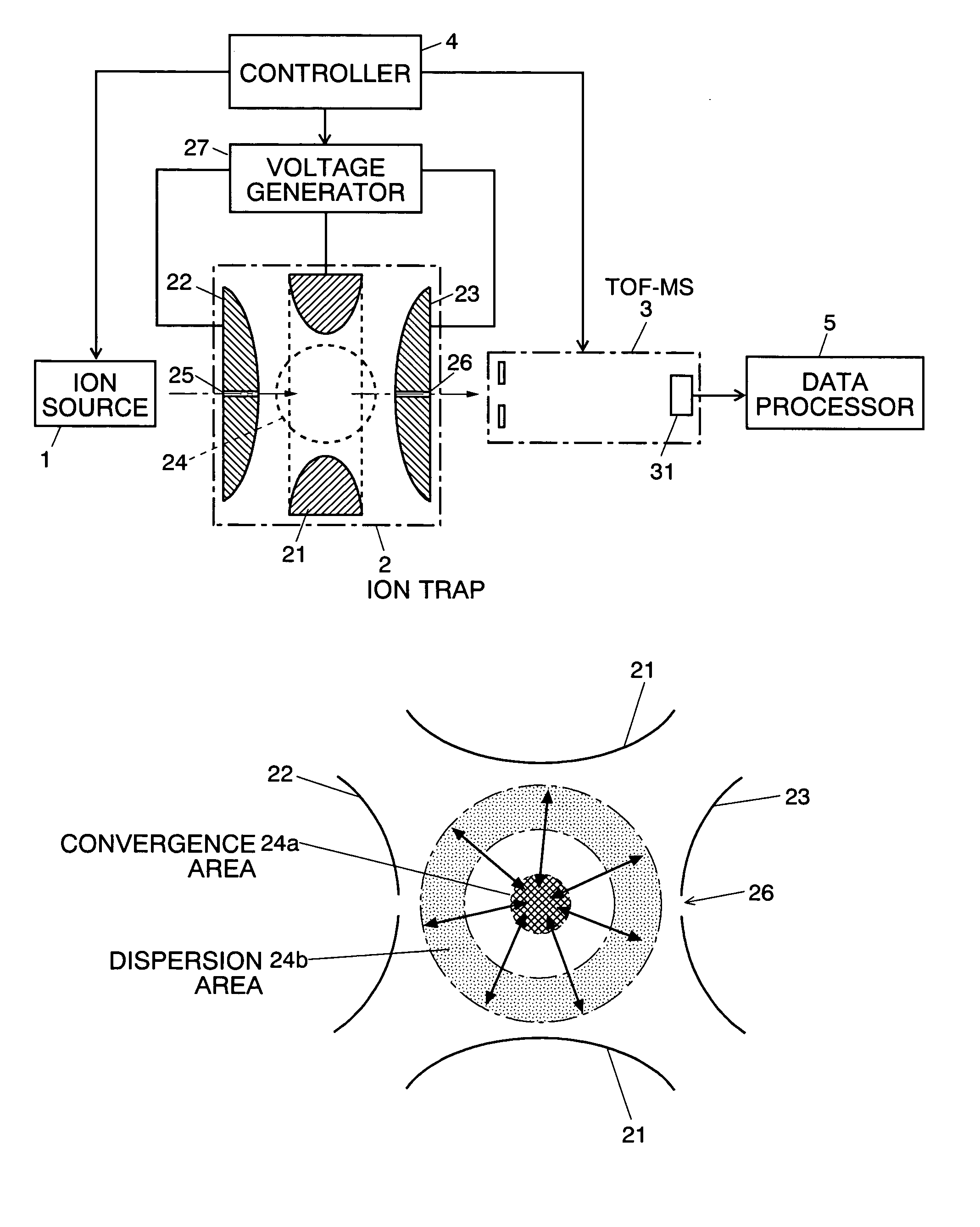
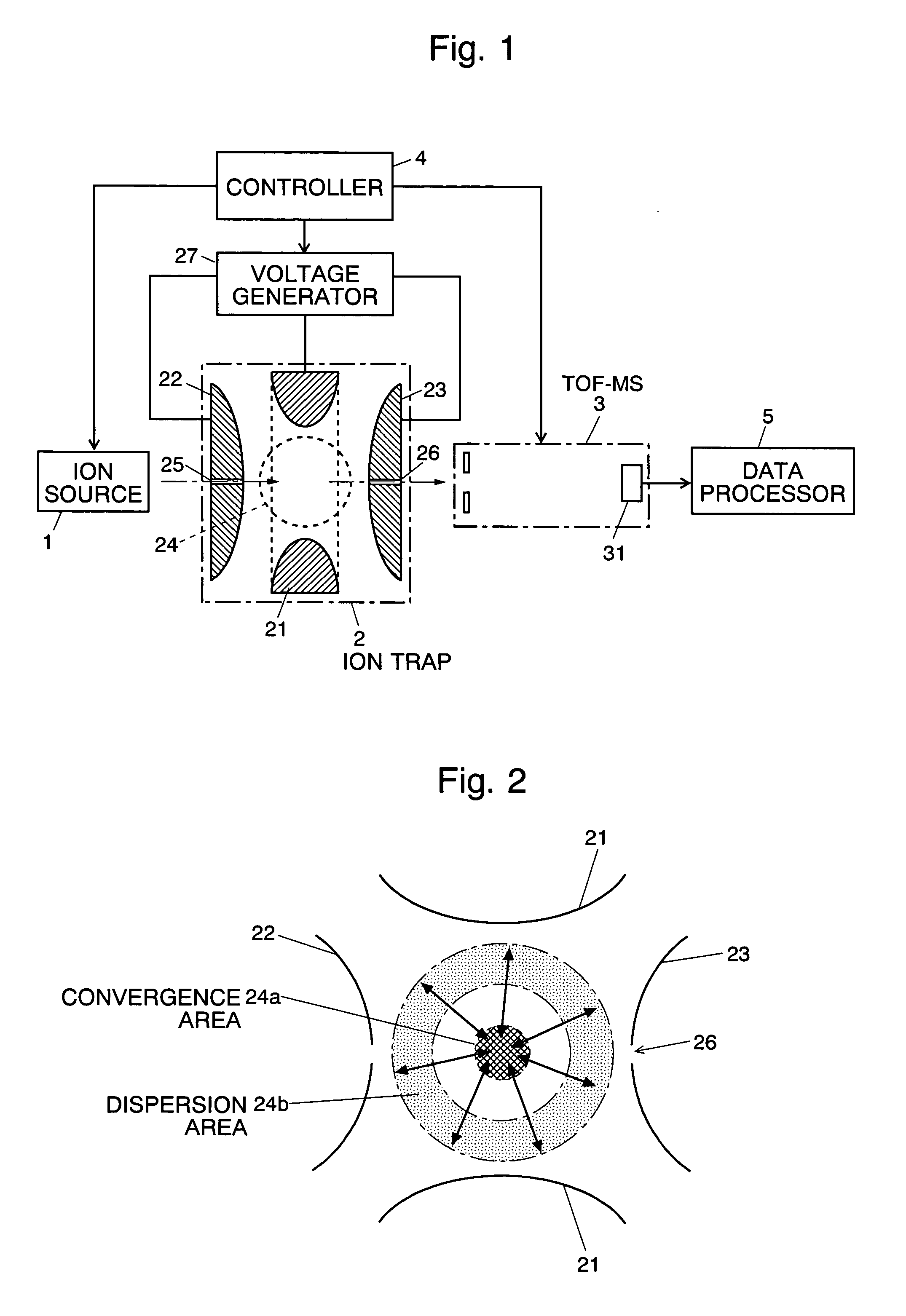
The present invention relates to a mass spectrometer that can minimize the variation in the starting point of ions when they are ejected from an ion trap and analyzed by a mass analyzer. This is achieved by controlling the time of changing the voltage from an ion trapping voltage to an ion ejecting voltage according to the polarity of the electric charge of ions to be ejected from the ion trap. This ensures that ions are ejected when they are converging or are converged in the ion trap, regardless of their polarity. This reduces errors in their flight time in the subsequent TOF-MS, improves the accuracy of mass analysis, and enhances mass resolution.

Problems solved by technology

This variation in the starting point causes a shift of the peaks of the mass spectrum, which makes the determination of the exact mass to charge ratio difficult and deteriorates the mass resolution of the mass spectrometer.

Method used


Image

  • Mass spectrometer with an ion trap
  • Mass spectrometer with an ion trap
  • Mass spectrometer with an ion trap

Examples


Embodiment Construction

[0021]A mass spectrometer using an ion trap is described as an embodiment of the present invention using FIGS. 1-3. FIG. 1 uses the same numbers for the same elements as in FIG. 4.

[0022]The ion source 1, the ion trap 2 and the TOF-MS 3 are placed in a vacuum chamber which is not shown. To the ring electrode 21, and the end cap electrodes 22, 23 are applied respective voltages from the voltage generator 27. The voltage is a DC voltage, an AC (RF) voltage or a superposition of the both voltages. The amplitude of the voltage and the time of voltage application are controlled by the controller 4 which is composed of a CPU and other electronic devices. The controller 4 controls the whole system including the ion trap 2, the ion source 1 and the TOF-MS 3.

[0023]The basic operation of the mass spectrometer of the present embodiment is as follows. The ion source 1 ionizes the molecule or atom of an object sample with an appropriate ionizing method. The ions generated in the ion source 1 are ...


PUM

PropertyMeasurementUnit
mass to charge ratioaaaaaaaaaa
mass to charge ratiosaaaaaaaaaa

Abstract

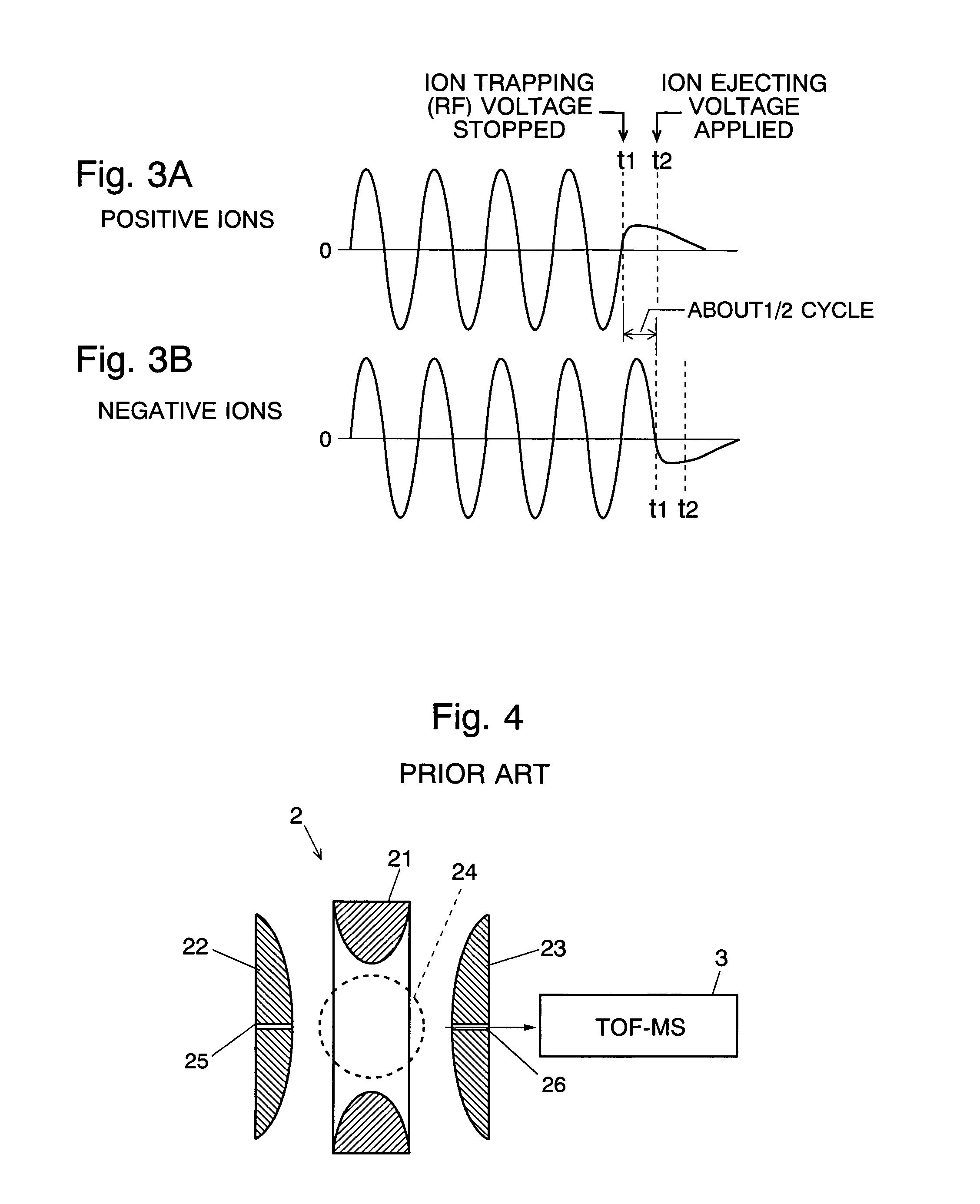
In the mass spectrometer of the present invention, the controller controls the time of changing the voltage applied to the electrode or electrodes of the ion trap from the ion trapping voltage to the ion ejecting voltage according to the polarity of the electric charge of ions to be ejected from the ion trap. Since positively charged ions and negatively charged ions move in the same direction if the phases of the RF voltage for generating the ion trapping electric field in the ion trap are reversed, the controller may reverse the phase of the RF voltage for trapping ions according to the polarity of the electric charge of ions when the ion ejecting time is fixed, irrespective of the polarity of the electric charge of ions to be ejected. Alternatively, the controller may change the ion ejecting time by half a cycle of the RF voltage depending on the polarity of the electric charge of ions when the ion trapping RF voltage is maintained the same. Owing to such a control, the ions are ejected when they are converging or are converged in the ion trap irrespective of the polarity of the electric charge of the ions. This minimizes the variation in the starting point of ions ejected from the ion trap, and reduces errors in their flight time in the subsequent TOF-MS, whereby the accuracy of the mass analysis is improved and the mass resolution is enhanced.

Description

[0001]The present invention relates to mass spectrometers equipped with an ion trap and a mass analyzer, where the ion trap traps and stores ions with appropriate electric fields and the mass analyzer analyzes the mass to charge ratio of ions ejected from the ion trap.BACKGROUND OF THE INVENTION[0002]In a time of flight mass spectrometer (TOF-MS), for example, ions are accelerated and introduced into a flight space where no electric or magnetic field is present, and they are separated by their mass to charge ratios based on the time of flight until they enter an ion detector. For the ion source of the TOF-MSs, an ion trap is often used.[0003]A typical ion trap 2 is composed of a ring electrode 21 and a pair of end cap electrodes 22 and 23, where the ring electrode 21 is placed between them, as shown in FIG. 4. Normally, a radio frequency (RF) voltage is applied to the ring electrode 21 to form a quadrupole electric field in an ion trap space 24 defined by the ring electrode 21 and t...

Claims


Application Information

Patent Timeline
Patent Type & Authority Patents(United States)
IPC IPC(8): H01J49/42H01J49/00H01J49/40G01N27/62
CPCH01J49/40H01J49/424
Inventor YAMAGUCHI, SHINICHIKAWATO, EIZO
Owner SHIMADZU CORP
Learn More