Birefringence measurement apparatus, strain remover, polarimeter and exposure apparatus

a technology of birefringence and measurement apparatus, applied in the direction of optical radiation measurement, photomechanical apparatus, instruments, etc., can solve the problems of increasing the demand for reducing the residual stress in the optical element, the inability of conventional optical glass to be used in such a wavelength region, and the deterioration of residual stress optical performan

Inactive Publication Date: 2007-07-31
CANON KK
View PDF19 Cites 12 Cited by
  • Summary
  • Abstract
  • Description
  • Claims
  • Application Information

AI Technical Summary

Benefits of technology

[0010]Accordingly, it is an exemplified object of the present invention to provide a birefringence measurement apparatus tha...

Problems solved by technology

A conventional optical element is available to an optical system down to a wavelength region for the i-line, but conventional optical glass cannot be used for such a wavelength region as covers the KrF and ArF excimer lasers and the F2 laser due to its low transmittance.
The residual stress deteriorates optical performance.
A demand for the reduced residual stress in the optical element has become increasingly strict for recent more precise optical systems and denser semiconductor devices, and the conventional birefringence measurement methods have faced difficulti...

Method used


Image

  • Birefringence measurement apparatus, strain remover, polarimeter and exposure apparatus
  • Birefringence measurement apparatus, strain remover, polarimeter and exposure apparatus
  • Birefringence measurement apparatus, strain remover, polarimeter and exposure apparatus

Examples


first embodiment

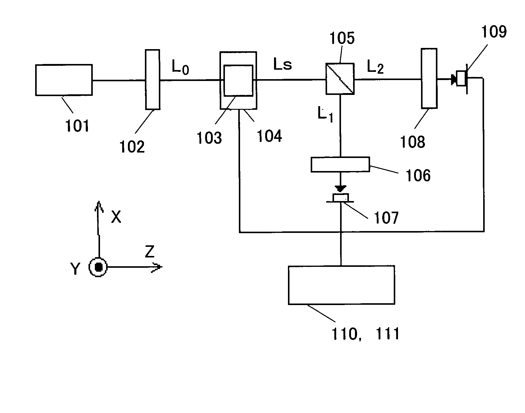
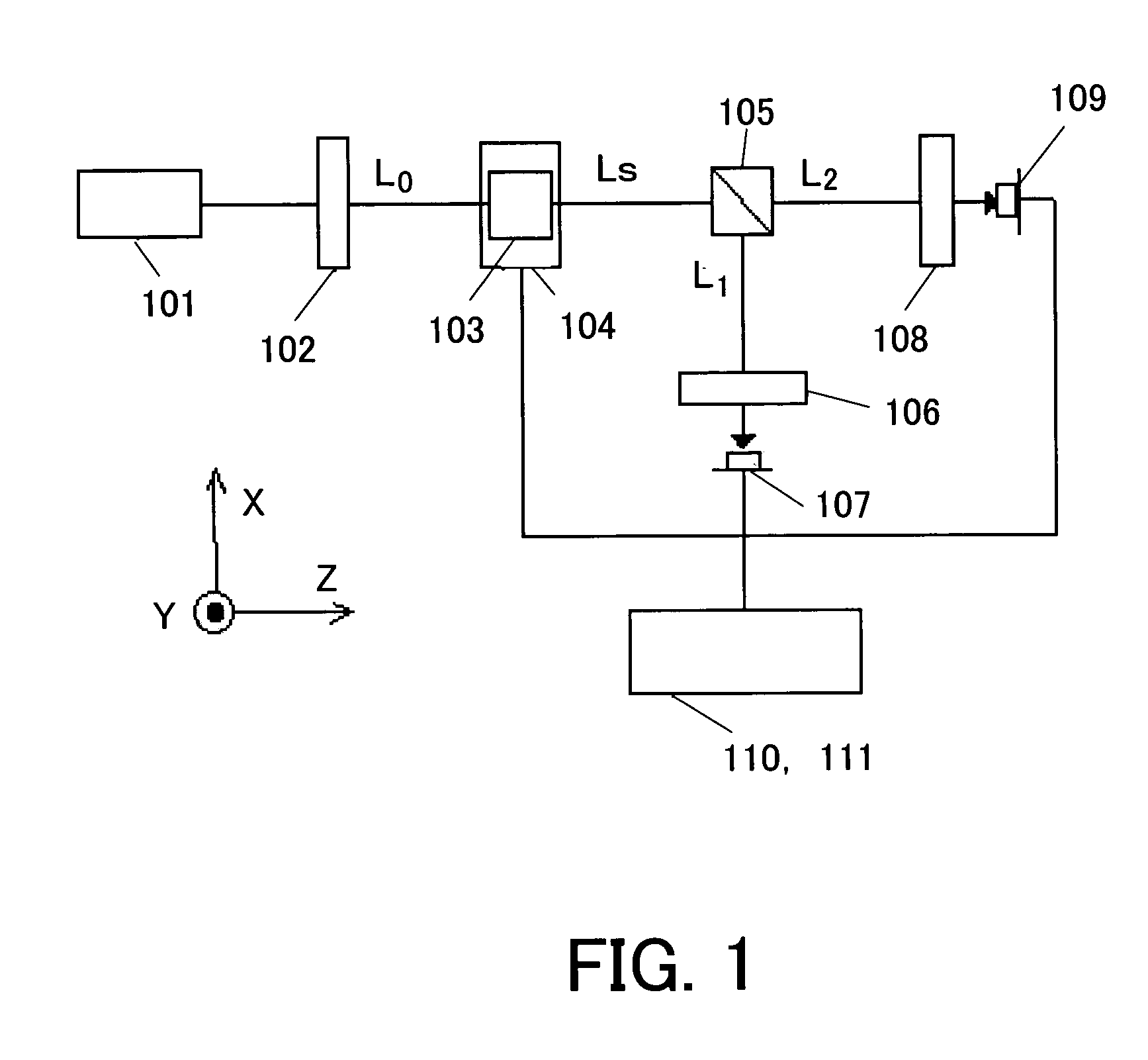
[0066]FIG. 1 is a schematic view of a structure of a birefringence measurement apparatus of a first embodiment according to the present invention. A description will be given of this birefringence measurement apparatus of the first embodiment with reference to FIGS. 1, 2 and 3.

[0067]FIG. 1 sets a Z-axis as a proceed direction of light emitted from a light source 101, an X-axis as a direction perpendicular to the Z-axis on a laser installation surface, and a Y-axis as a direction normal to the laser installation surface.

[0068]In FIG. 1, the birefringence measurement apparatus of the first embodiment includes a light source 101, a polarization element 102, an object to be measured 103, a sample stage 104, a beam splitter means 105, polarization elements 106 and 108, light-quantity detector means 107 and 109, an operation part 110, and a controller 110.

[0069]The light emitted from the light source 101 is incident upon the object 103 after converted into a linearly polarized light L0 vi...

embodiment 2

[0117]FIG. 4 is a schematic view of a birefringence measurement apparatus of a second embodiment according to the present invention. A description will be given of the birefringence measurement apparatus of the second embodiment with reference to FIG. 4.

[0118]The instant embodiment uses similar structure to that of the first embodiment except that the instant embodiment is configured to use rotational control means for the polarization elements 102, 106, and 108. A detailed description of the common structure will be omitted by assigning corresponding reference numerals to the last two digits, and different portion from the first embodiment will be mainly discussed.

[0119]In FIG. 4, the birefringence measurement apparatus of the second embodiment includes a light source 401, a polarization element 402, an object to be measured 403, a sample stage 404, beam splitter means 405, polarization elements 406 and 408, light-quantity detector means 407 and 409, an operation part 410, and a co...

third embodiment

[0142]FIGS. 5 and 6 are schematic views of a strain remover of a third embodiment according to the present invention. A description will be given of the strain remover of the third embodiment with reference to FIGS. 5 and 6.

[0143]The instant embodiment uses similar structure to the birefringence measurement apparatus of the second embodiment except that the instant embodiment is configured to store an object to be measured 404 in a heat treatment part. A detailed description of the common structure will be omitted by assigning corresponding reference numerals to the last two digits, and different portion from the second embodiment will be mainly discussed.

[0144]In FIG. 5, the strain remover of the third embodiment includes a light source 501, a polarization element 502, an object to be measured 503, a heat treatment part 504, a beam splitter means 505, polarization elements 506 and 508, light-quantity detector means 507 and 509, an operation part 510, and a controller 511.

[0145]The ...


PUM


Abstract

A birefringence measurement apparatus for calculating information of polarization of light emitted from an object to be measured includes a light source, a first polarization element for extracting a beam in a specific polarization direction from light emitted from the light source, a sample stage that holds an object to be measured, at least one beam splitting unit that splits the light emitted from the object into two beams having the same polarization as that of the light emitted from the object, at least two second polarization elements for extracting beams in a specific polarization direction of the light split by the beam splitting unit, at least two light-quantity detectors for detecting light quantity of beams that have transmitted through the second polarization element, and an operation part for operating a light quantity received by the light-quantity detectors.

Description

[0001]This application claims a benefit of foreign priority based on Japanese Patent Applications No. 2002-191706, filed on Jul. 1, 2002, and Japanese Patent Application No. 2002-380014, filed on Dec. 27, 2002, each of which is hereby incorporated by reference herein in its entirety as if fully set forth herein.BACKGROUND OF THE INVENTION[0002]The present invention relates to a birefringence measurement apparatus for calculating a retardation magnitude and an azimuth of a principal axis of an object retardance to be measured, a strain remover having the birefringence measurement apparatus, a polarimeter or polarization detector that includes the birefringence measurement apparatus, and an exposure apparatus that includes the polarimeter.[0003]As the need for smaller and thinner electronic apparatuses grows in recent years, finer semiconductor devices mounted in these electronic apparatuses have been increasingly demanded, and various proposals have been made for higher exposure reso...

Claims


Application Information

Patent Timeline
IPC IPC(8): G01J4/00G01J4/04G01N21/23G03F7/20
CPCG01J4/04G01N21/23G03F7/70566G03F7/70591G03F7/70966
Inventor KISHIKAWA, YASUHIROTAKEUCHI, SEIJI
Owner CANON KK
Why Eureka
Try Eureka