
Electric chemical capacitor, and method and apparatus for manufacturing electrode for electric chemical capacitor

a technology of chemical capacitors and capacitors, which is applied in the manufacture of capacitors, casings/cabinets/drawers, electrical equipment casings/cabinets/drawers, etc., can solve problems such as failure to short circuit, and achieve the effects of effective prevention of short circuit, high reliability, and high precision

Active Publication Date: 2007-07-31
TDK CORPARATION
View PDF17 Cites 11 Cited by
  • Summary
  • Abstract
  • Description
  • Claims
  • Application Information

AI Technical Summary

Benefits of technology

The invention aims to prevent short-circuiting in an electric chemical capacitor caused by an undercoat layer. It provides a method and apparatus for manufacturing an electrode with high precision, controlling the position where a polarized electrode layer is formed. This prevents the undercoat layer from abutting against adjacent electrodes or collector layers, reducing the risk of failure.

Problems solved by technology

Thus, there is a fear that a failure of short-circuit is caused.
Such a problem becomes particularly important when a structure in which a large number of electrodes are laminated through separators is used.

Method used


Image

  • Electric chemical capacitor, and method and apparatus for manufacturing electrode for electric chemical capacitor
  • Electric chemical capacitor, and method and apparatus for manufacturing electrode for electric chemical capacitor
  • Electric chemical capacitor, and method and apparatus for manufacturing electrode for electric chemical capacitor

Examples


first embodiment

[0044]A preferred embodiment of the invention will be described below in detail with reference to the accompanying drawings.

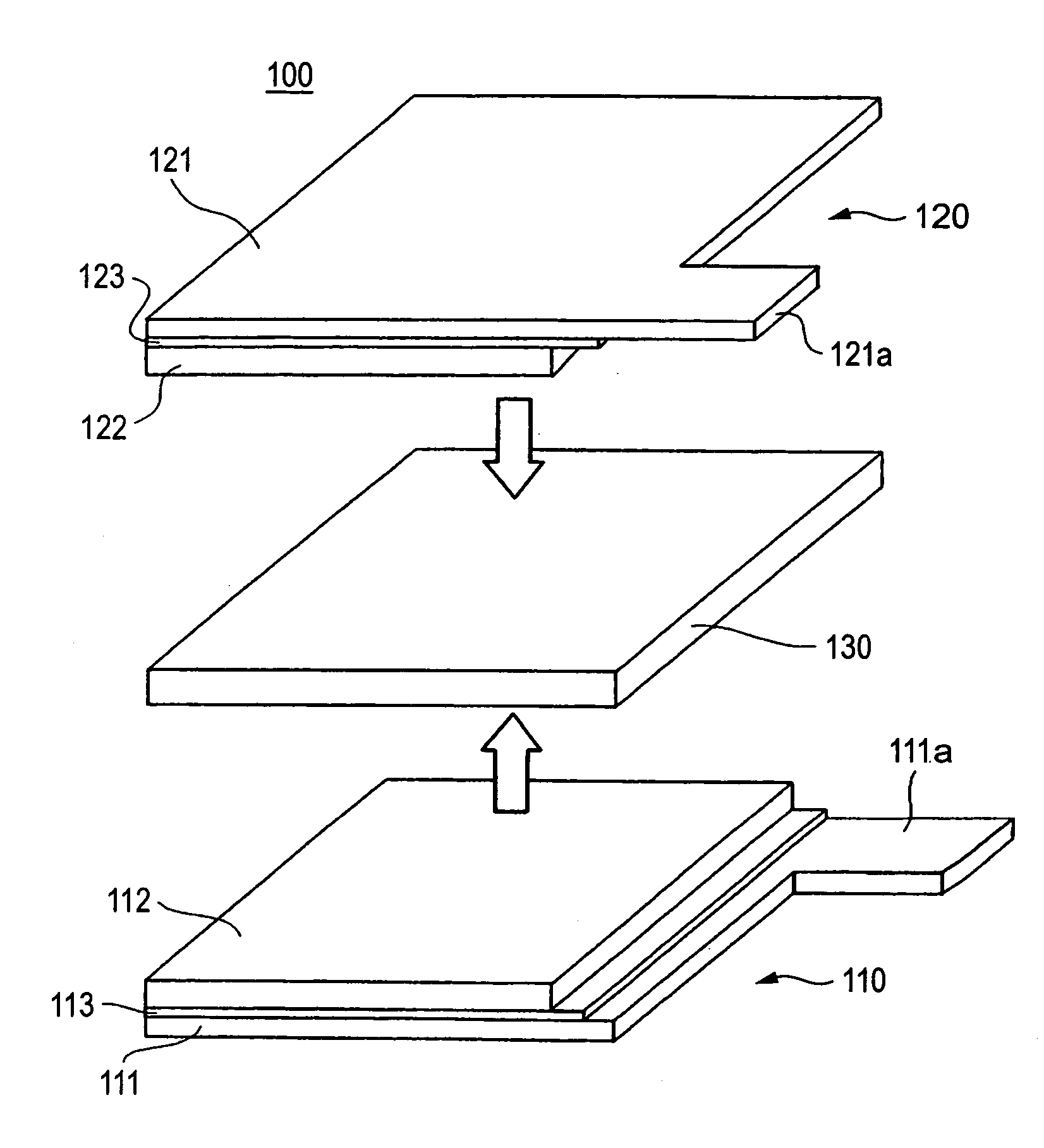
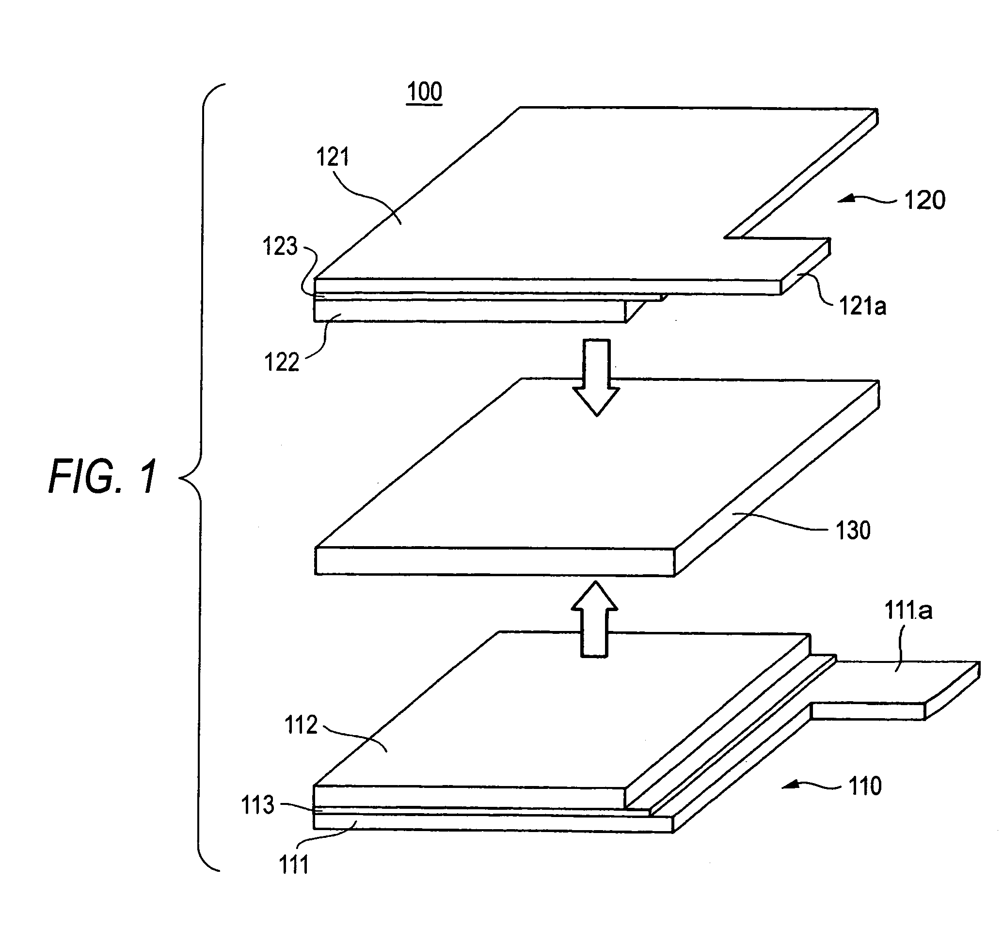
[0045]FIG. 1 is an exploded perspective view showing a state where an electric chemical capacitor 100 has not yet been assembled according to a preferred embodiment of the invention.

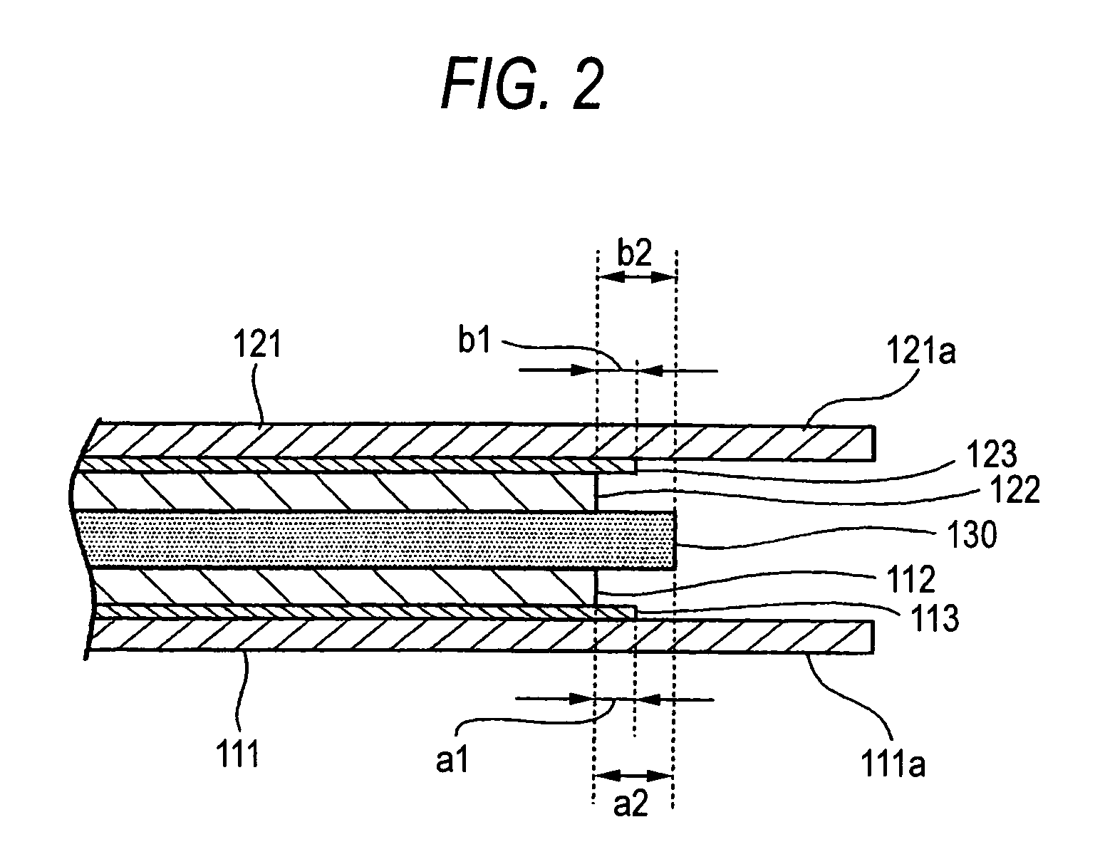
[0046]As shown in FIG. 1, the electric chemical capacitor 100 according to this embodiment includes a first electrode 110, a second electrode 120 and a separator 130 as its main components. The separator 130 is put between the first and second electrodes 110 and 120. The first electrode 110 is constituted by a collector 111, a polarized electrode layer 112 and an undercoat layer 113 provided therebetween. An extractor electrode 111a is provided in the collector 111. In the same manner, the second electrode 120 is constituted by a collector 121, a polarized electrode layer 122 and an undercoat layer 123 provided therebetween. An extractor electrode 121a is provided in the collector 1...

second embodiment

[0098]A preferred embodiment of the invention will be described below in detail with reference to the accompanying drawings.

[0099]FIG. 10 is a schematic view showing a structure of electric chemical capacitor electrode manufacturing apparatus according to a preferred embodiment of the invention.

[0100]As shown in FIG. 10, electric chemical capacitor electrode manufacturing apparatus 600 according to the embodiment has a supply roll 601 on which a belt-like collector 516 is wound, a take-up roll 602 rotatable in a predetermined velocity to thereby take up a laminate 520 of a collector 516 and a polarized electrode layer 518, an coater portion 610, a drier portion 620 and a roll press portion 630. The coater portion 610, the drier portion 620 and the roll press portion 630 are provided between the supply roll 601 and the take-up roll 602 in that order. In such a manner, the electric chemical capacitor electrode manufacturing apparatus 600 according to this embodiment has a configuratio...


PUM


Abstract

An electric chemical capacitor includes first and second electrodes each including a collector 111, 121, a polarized electrode layer 112, 122 and an undercoat layer 113, 123 for bonding the collector and the polarized electrode layer with each other, and a separator put between the first and second electrodes so that the polarized electrode layers 112 and 122 face each other, wherein an end portion of each undercoat layer 113, 123 is located in the same position as or on the outer side of an end portion of the corresponding polarized electrode layer 112, 122, and located on the inner side of an end portion of the separator 130. Thus, the polarized electrode layers can be prevented from peeling from the collector. Further, the undercoat layers can be prevented from abutting against each other, and the undercoat layer of one electrode and the collector of the other electrode can be prevented from abutting against each other.

Description

TECHNICAL FIELD [0001]The present invention relates to an electric chemical capacitor, and particularly relates to an electric chemical capacitor having an electrode provided with an undercoat layer. In addition, the invention relates to a method and apparatus for manufacturing an electrode for an electric chemical capacitor, and particularly relates to a method and apparatus for manufacturing an electrode for an electric chemical capacitor, in which the position where a polarized electrode layer is formed can be controlled with high precision.BACKGROUND ART [0002]Electric chemical capacitors such as electric double layer capacitors and so on can be made smaller in size and lighter in weight easily. Therefore, electric chemical capacitors are expected, for example, as backup power supplies for portable equipment (miniature electronic equipment) or the like, auxiliary power supplies for electric vehicles or hybrid vehicles, etc. Thus, various examinations have been made to improve th...

Claims


Application Information

Patent Timeline
Patent Type & Authority Patents(United States)
IPC IPC(8): H01G9/00H01G11/12H01G11/28H01G11/86H01G13/00
CPCH01G9/016H01G9/058H01G9/155H01G11/12H01G11/28H01G11/86H01G13/006Y02E60/13H01G11/74H01G11/22
Inventor HINOKI, KIYONORIMIYAKI, YOUSUKEKATAI, KAZUOTANAKA, HIDEKIICHIKI, TSUYOSHI
Owner TDK CORPARATION
Learn More