
On-vehicle handsfree system and mobile terminal thereof

a technology of hands-free system and mobile terminal, which is applied in the field of hands-free system, can solve the problems inefficient occupation of limited internal space, and inability to easily use peripheral devices for hands-free system,

Inactive Publication Date: 2007-07-31
PANASONIC CORP
View PDF13 Cites 37 Cited by
  • Summary
  • Abstract
  • Description
  • Claims
  • Application Information

AI Technical Summary

Benefits of technology

[0013]It is accordingly an object of the present invention to provide a compact on-vehicle handsfree system that does not need peripheral devices exclusively for the handsfree system when peripheral devices of the handsfree system such as the microphone, the speaker, the camera, and the display are included in the car audio and video devices.
[0014]Another object of the present invention is to provide an easy-to-operate, on-vehicle handsfree system that requires no camera adjustment and ensures easy operation and safe driving using the control interface that has been designed for use in the in-car environment.
[0015]A further object of the present invention is to provide a convenient on-vehicle handsfree system that can be activated without troublesome operations such as to connect the mobile phone with the adapter via a cable and press a button.
[0020]Accordingly, a handsfree system is realized only by bringing a mobile terminal into the vehicle without bringing into peripheral devices exclusively for the handsfree system according to the present invention. As a result, the internal space of the vehicle is not wastefully occupied with or disordered by a lot of devices. In addition, the operation of the handsfree system such as volume control can be input using the car peripheral units, so that no special operation exclusively for the handsfree system is required. More specifically, the handsfree video phone can be operated using the control interface that has been designed for use in the in-car environment, so that the handsfree system that ensures easy operation and safe driving is realized without troublesome setting.
[0021]The above-mentioned second object may be achieved by an on-vehicle handsfree system in which set information of a car camera is stored in a mobile terminal and the car camera is differently set for each user using the set information at the start of the handsfree status. The second object may also be achieved by an on-vehicle handsfree system in which set information of a car camera related to a mobile terminal is stored in one of a car microphone, a car speaker, a car camera, and a car display, which each are car peripheral units, and the car camera is differently set for each user using the set information stored in the car peripheral unit at the start of the handsfree status. In this way, by storing the set information of the car camera that has been customized for each user in the mobile terminal, for instance, the car camera can be adjusted for the user only by bringing a mobile terminal into the vehicle.
[0022]The above-mentioned third object may be achieved by an on-vehicle handsfree system in which the mobile terminal is switched between a stand alone status and a handsfree status according to the operation of the engine key, the input operation of a mobile terminal or a car peripheral unit, the status of communication linkage between a mobile terminal and a car peripheral unit, the status of setting a mobile terminal on the telephone holder, or the like. As a result, the handsfree system can be activated without troublesome operations such as connecting the mobile terminal with the adapter via a cable and pressing a button.

Problems solved by technology

This is troublesome.
This is problematic.
Although these audio and video devices also include peripheral devices such as a microphone, a speaker, a display, and a remote controller, these peripheral devices cannot be easily used for the handsfree system.
As a result, the limited internal space is inefficiently occupied.
The video phone terminal, however, has a small display that is not useful to watch the screen.
This is also troublesome.

Method used


Image

  • On-vehicle handsfree system and mobile terminal thereof
  • On-vehicle handsfree system and mobile terminal thereof
  • On-vehicle handsfree system and mobile terminal thereof

Examples


first embodiment

(The First Embodiment)

[0043]The following is an explanation of the on-vehicle handsfree video phone system according to the first embodiment of the present invention with reference to figures.

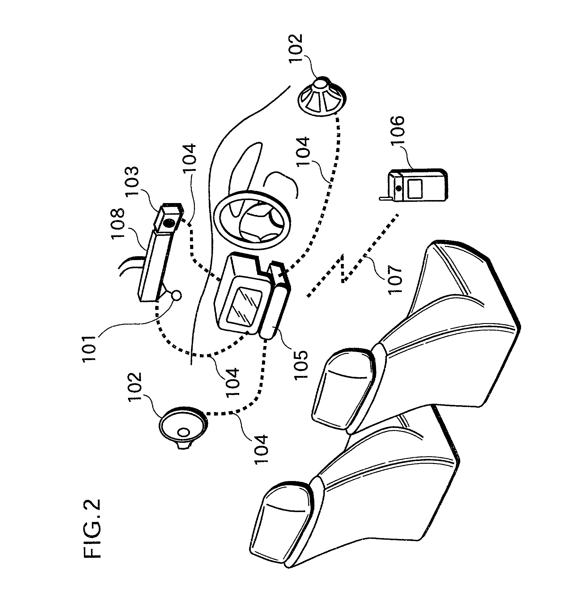
[0044]FIG. 2 shows the structure of the on-vehicle handsfree video phone system according to the first embodiment of the present invention. The handsfree video phone system includes a microphone 101, a speaker 102, a camera 103, a connecting cable 104, an instrument panel 105, a video phone terminal 106, a wireless communication medium 107, and a room mirror 108.

[0045]The overall operation of the handsfree video phone system will be explained below.

[0046]Car devices such as the microphone 101, the speaker 102, and the camera 103 are connected with the instrument panel 105 via the connecting cable 104. Note that these car devices may be connected via a bus or a wireless medium instead of the connecting cable 104.

[0047]The video phone terminal 106 is a mobile wireless communication device that en...

second embodiment

(The Second Embodiment)

[0080]Here, an explanation of the on-vehicle handsfree video phone system according to the second embodiment of the present invention will be given with reference to figures.

[0081]FIG. 8 shows the structure of the on-vehicle handsfree video phone system according to the second embodiment of the present invention. The handsfree video phone system includes a headset 501, a wireless camera 502, an instrument panel 503, a video phone terminal 106, a wireless communication medium 107, and a room mirror 108. In the second embodiment (including figures), the same reference numbers are given to the same components as in the first embodiment. Also, the explanation will focus on only different components.

[0082]Here, an overall explanation of the operations of the handsfree video phone system will be given.

[0083]Unlike the first embodiment, the wireless headset 501 is used instead of a microphone and a speaker. In terms of the camera, the wireless camera 50 is used. The ...

third embodiment

(The Third Embodiment)

[0102]Here, an explanation of the on-vehicle handsfree video phone system according to the third embodiment of the present invention with reference to figures.

[0103]FIG. 11 shows the structure of the on-vehicle handsfree video phone system according to the third embodiment of the present invention. The handsfree video phone system includes a video phone terminal 801, an instrument panel 802, a headset 501, a wireless camera 502, a wireless communication medium 107, and a room mirror 108.

[0104]An overall explanation of the handsfree video phone system will be given below.

[0105]Unlike in the second embodiment, the video phone terminal 801 that is brought into the vehicle is directly connected with the headset 501, the wireless camera 502, and the instrument panel 802, which belong to the vehicle, via the wireless communication medium 107 in the present embodiment. As a result, the media demultiplex is performed in the video phone terminal 801. Accordingly, the in...


PUM


Abstract

A handsfree video phone system includes a video phone terminal and a car device in which a microphone, a speaker, and a camera are connected with an instrument panel via a cable. The video phone terminal is connected with the instrument panel via a wireless communication medium. When the video phone terminal is brought into the vehicle, the instrument panel informs the video phone terminal of the attribute information on the system structure. According to the attribute information, the video phone terminal switches the paths of multiplexed audio-video data so as to replace a microphone, a speaker, a camera, and a display that have been built in the video phone terminal with the microphone, the speaker, the camera, and a display of the instrument panel when the status changes to the communication status.

Description

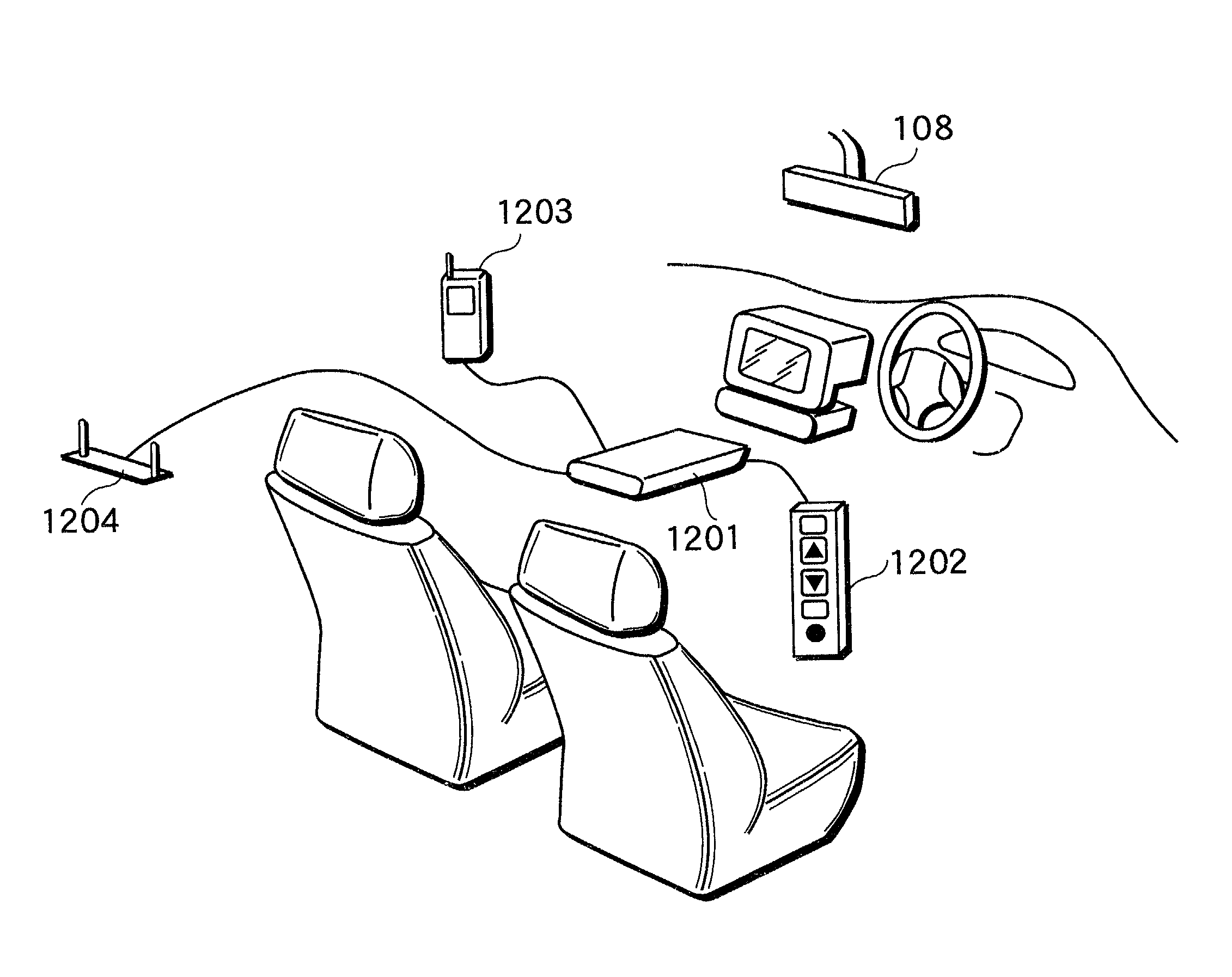
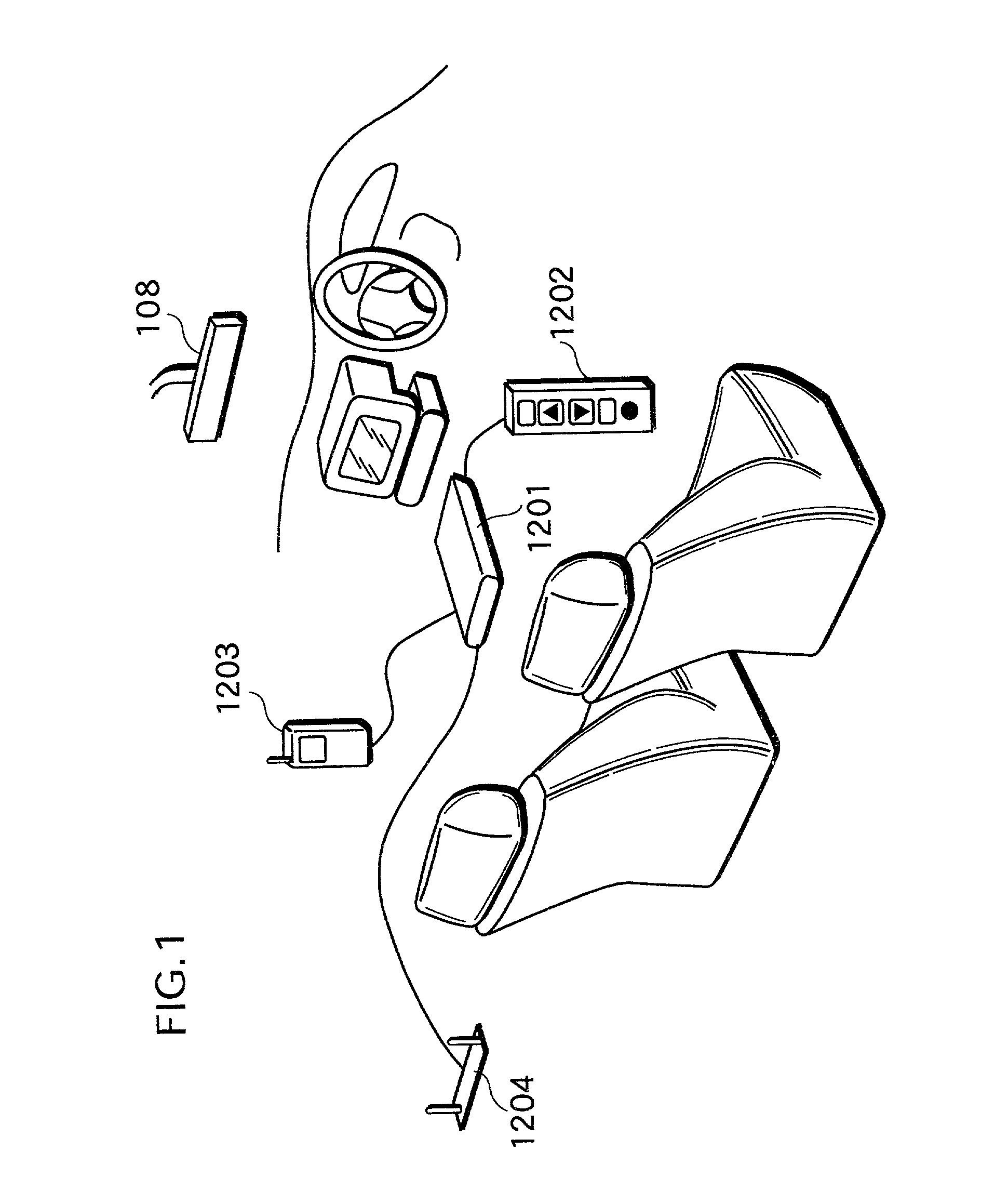
BACKGROUND OF THE INVENTION[0001](1) Field of the Invention[0002]The present invention relates to a handsfree system for making a handsfree telephone call in an automobile, and especially relates to an on-vehicle handsfree system that is realized in combination with car devices such as a camera, a microphone a speaker, and a display.[0003](2) Description of the Prior Art[0004]For the safe use of a mobile phone in an automobile, on-vehicle handsfree systems have become popular.[0005]The conventional on-vehicle handsfree system will be explained with reference to FIG. 1. FIG. 1 schematically shows the structure of a conventional on-vehicle handsfree system.[0006]The conventional handsfree system includes an adapter 1201, a microphone-built-in control switch assembly 1202, a mobile phone 1203, and an external antenna 1204. The adapter 1201 is equipped with connectors to be connected with the microphone-built-in control switch assembly 1202, the mobile phone 1203, and the external anten...

Claims


Application Information

Patent Timeline
Patent Type & Authority Patents(United States)
IPC IPC(8): H04M1/00H04B1/38H04M1/60H04N7/14
CPCH04M1/6091H04N7/142H04N7/148H04B1/40
Inventor KITAO, MITSURUKUROSAKI, TOSHIHIKOHATAKEYAMA, TAKESHITOMODA, MASAKI
Owner PANASONIC CORP
Learn More