
Structure for disposing fuel tank for straddle-type vehicle

a technology for straddling vehicles and structures, which is applied in the direction of cycle equipment, transportation items, cycle equipment, etc., can solve the problems of difficulty in forming, difficulty in forming seam-welding portions, and insufficient appearance of the attachment of protection members

Active Publication Date: 2007-08-07
YAMAHA MOTOR CO LTD
View PDF5 Cites 26 Cited by
  • Summary
  • Abstract
  • Description
  • Claims
  • Application Information

AI Technical Summary

Benefits of technology

[0009]In view of the foregoing, it is, therefore, an advantage of the present invention to provide a fuel tank capable of being easily formed and to provide a structure for disposing a fuel tank for a straddle-type vehicle capable of improving quality in appearance of a portion where the fuel tank is disposed.
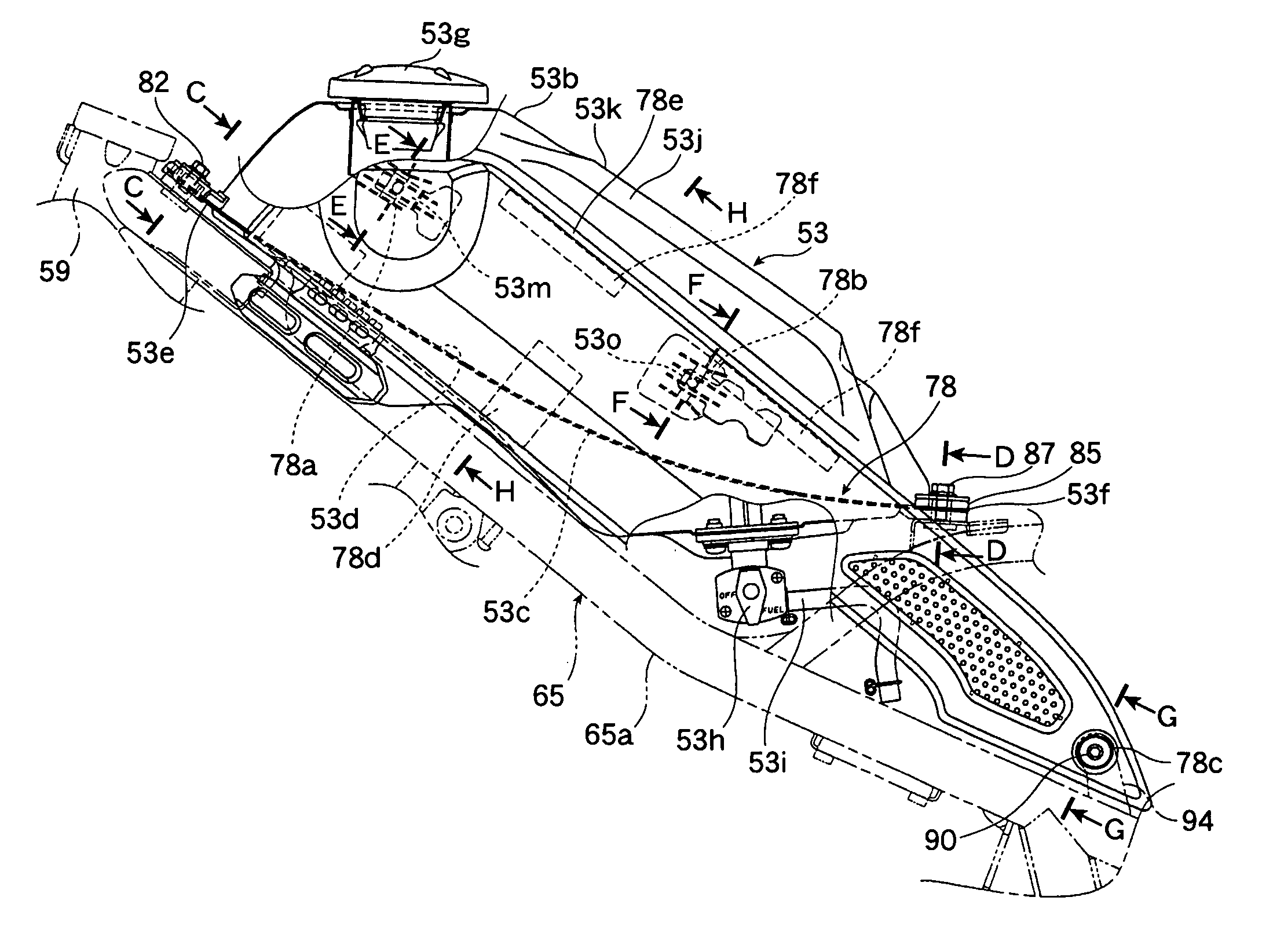
[0010]In order to solve the foregoing problems, an embodiment of the present invention provides a structure for disposing a fuel tank for a straddle-type vehicle which is located closely behind a head pipe of the straddle-type vehicle and exposed upward at the upper surface side. The fuel tank has a two-piece structure made up of a lower panel and an upper panel, each having a flange which is formed at the side peripheral edge thereof and joined with the other flange to form the fuel tank. The fuel tank is located in a manner such that the upper panel is exposed upward at the upper surface portion, and in which the fuel tank at the side portions is provided with tank side covers each having a specified vertical width to cover the flange.
[0011]An embodiment of the present invention provides a structure for disposing a fuel tank for a straddle-type vehicle which is located closely behind a head pipe of the straddle-type vehicle and exposed upward at the upper surface side. The fuel tank has a two-piece structure made up of a lower panel and an upper panel, each having a flange which is formed at the side peripheral edge thereof and joined with the other flange to form the fuel tank. The fuel tank is located in a manner such that the upper panel is exposed upward at the upper surface portion, and in which the upper surface portion of the upper panel assumes a mountainous shape in a section taken along the lateral direction of the vehicle, with a line which runs in the longitudinal direction of the vehicle, as an edge line.
[0012]A further embodiment of the present invention provides a structure for disposing a fuel tank for a straddle-type vehicle which is located closely behind a head pipe of the straddle-type vehicle and exposed upward at the upper surface side. The fuel tank has a two-piece structure made up of a lower panel and an upper panel, each having a flange which is formed at the side peripheral edge thereof and joined with the other flange to form the fuel tank. The fuel tank is located in a manner such that the upper panel is exposed upward at the upper surface portion, and in which the upper surface portion of the upper panel assumes a mountainous shape in a section taken along the lateral direction of the vehicle. The dimension R of the mountainous top is smaller than the height, the distance from the bottom to the top, of the fuel tank.
[0013]The fuel tank is disposed to be inclined along main frames extending obliquely downward to the rear from the head pipe. Also, the fuel tank is formed to be sloped such that the flanges at the front edge side are placed at a lower position than at the rear edge side when the fuel tank is placed with the upper surface portion positioned generally horizontally.
[0014]The front edge of the flanges is mounted on the main frames at the inclined portions, and the rear edge of the flanges is mounted on seat frames for supporting a seat, at the horizontal portions.

Problems solved by technology

Thus, it is difficult to form the seam-welding portions on the tank outer plate and the tank bottom plate, respectively, with good accuracy by press forming.
However, when the tank outer plate and the tank bottom plate are not formed with a high degree accuracy, an optimum fit cannot be provided, or even when both plates are successfully fitted together, a gap may occur between the seam-welding portions resulting in a problem of difficulty in forming.
The protection member, however, only provides such functions, and attaching the protection member does not necessarily provide a good appearance.

Method used


Image

  • Structure for disposing fuel tank for straddle-type vehicle
  • Structure for disposing fuel tank for straddle-type vehicle
  • Structure for disposing fuel tank for straddle-type vehicle

Examples


Embodiment Construction

[0051]An embodiment of the present invention will be described below.

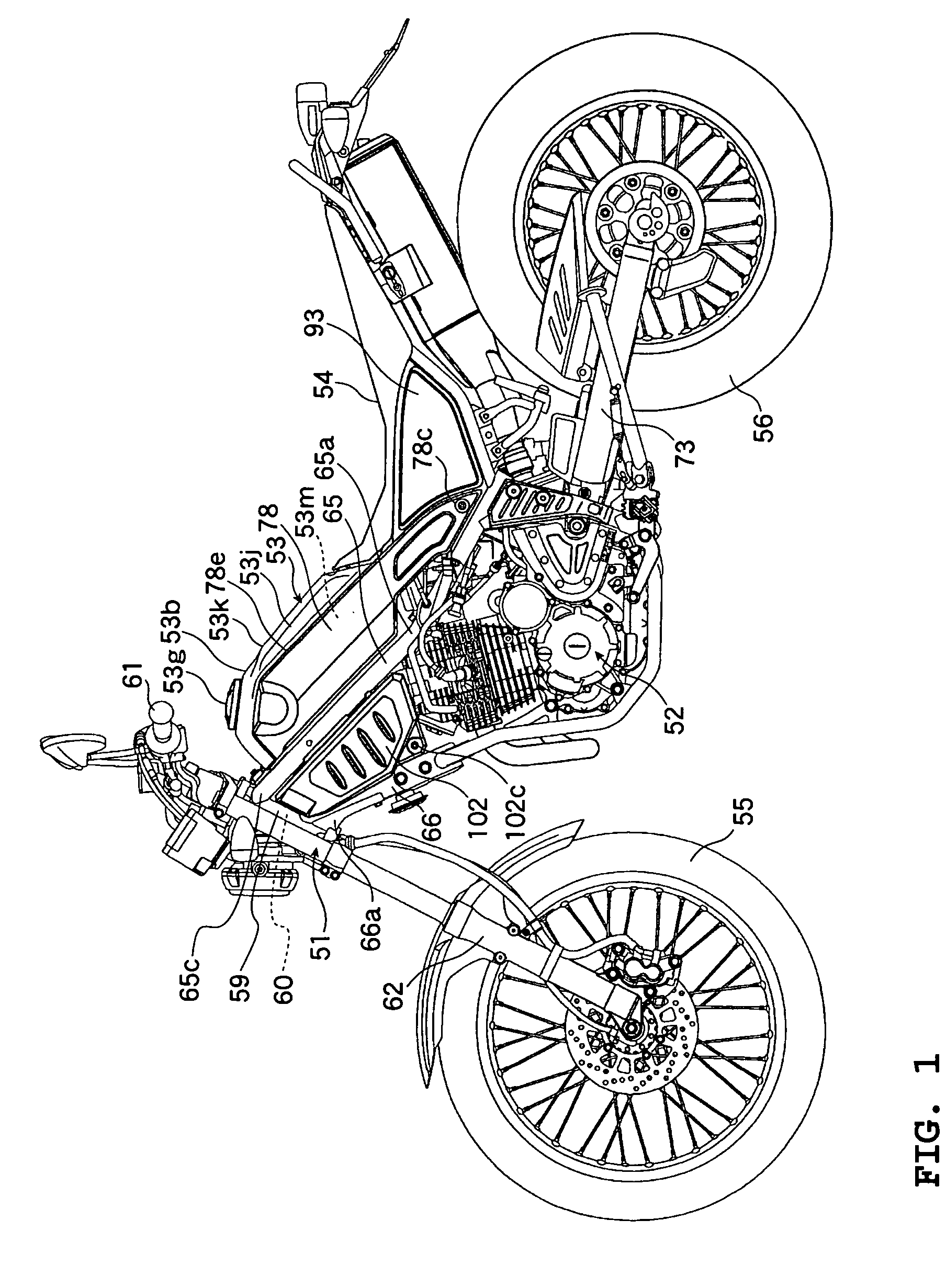
[0052]FIGS. 1 through 28 show an embodiment of the present invention.

[0053]The configuration of this embodiment will be first described. FIG. 1 shows a motorcycle as a “straddle-type vehicle.” This motorcycle is a so-called on- and off-road vehicle capable of running mainly on an unpaved road with a rough surface. It is designed to be small in width and weight, compared with the motorcycle designed for running on an ordinary road, in consideration of handleability of the body during running.

[0054]More specifically, reference numeral 51 in FIG. 1 denotes a body frame. An engine 52 is mounted on the body frame 51. A fuel tank 53 and a seat 54 are placed above the engine 52 and behind the fuel tank 53, respectively. Further, a front wheel 55 and a rear wheel 56 are disposed forward and rearward of the body frame 51, respectively.

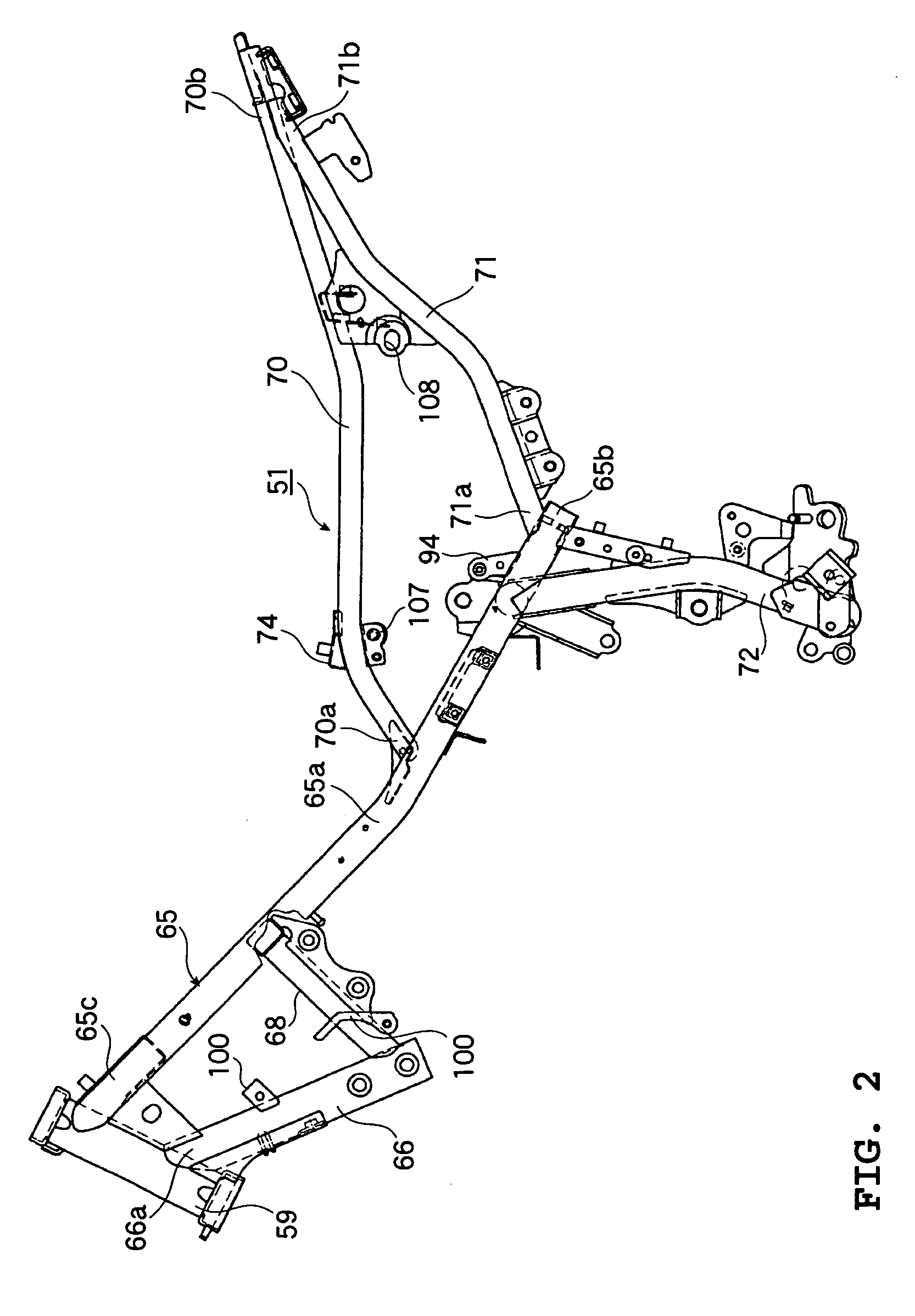
[0055]As shown in FIGS. 2 and 3, the body frame 51 has a cylindrical head pipe 59 at the f...


PUM


Abstract

A fuel tank for a straddle-type vehicle includes a two-piece structure made up of a lower panel and an upper panel, each panel having a flange which is formed at a side peripheral edge thereof and joined with the other flange to form the fuel tank, and side portions provided with tank side covers each having a specified vertical width to cover the flanges. The fuel tank is located in a manner such that the upper panel is exposed upward at an upper surface portion.

Description

BACKGROUND OF THE INVENTION[0001]1. Field of the Invention[0002]The present invention relates to a structure for disposing a fuel tank for a straddle-type vehicle such as a motorcycle.[0003]2. Description of the Related Art[0004]A conventional fuel tank for a motorcycle has a tank outer plate and a tank bottom plate which are seam-welded together, and a projecting fuel cock formed on the tank bottom plate. The fuel tank at the side of seam-welding portions is integrally formed with extended members projecting downward below the fuel cock. The extended members are provided with mounting portions of a front cowling and a side cover.[0005]When the fuel tank is removed from the body and placed on the ground or the like without using any jigs or the like, the extended members of the seam-welding portions function as the legs of the fuel tank so that the fuel cock can be protected. In addition, the extended members can also be used for mounting and supporting the front cowling and the sid...

Claims


Application Information

Patent Timeline
Patent Type & Authority Patents(United States)
IPC IPC(8): B62D61/02B60P3/22B62K11/00B62M7/00B62J9/40B62J23/00B62J35/00
CPCB62J35/00
Inventor MIYAKOZAWA, OKISAKAMOTO, MITSURUTAKETSUNA, MASATAKASHIMIZU, YUUJIARIMURA, MASATSUGU
Owner YAMAHA MOTOR CO LTD
Learn More