Delay clock track read back data to compensate time variance due to disk thermal expansion in spiral servo track writing

a technology of spiral servo and read-back data, which is applied in the direction of maintaining head carrier alignment, digital recording, instruments, etc., can solve the problems of starting points, reducing the density, and affecting the performance of the driv

Inactive Publication Date: 2007-08-07
SAMSUNG ELECTRONICS CO LTD
View PDF1 Cites 11 Cited by
  • Summary
  • Abstract
  • Description
  • Claims
  • Application Information

AI Technical Summary

Problems solved by technology

This variation in start points may be caused by system vibration, servo track writer positioning errors and other factors.
Inaccurate servo can lower the density and degrade the performance of the drive.
The relative movement in indices may change the start point for subsequently written spiral tracks leading to inaccurate servo writing.

Method used


Image

  • Delay clock track read back data to compensate time variance due to disk thermal expansion in spiral servo track writing
  • Delay clock track read back data to compensate time variance due to disk thermal expansion in spiral servo track writing
  • Delay clock track read back data to compensate time variance due to disk thermal expansion in spiral servo track writing

Examples


Embodiment Construction

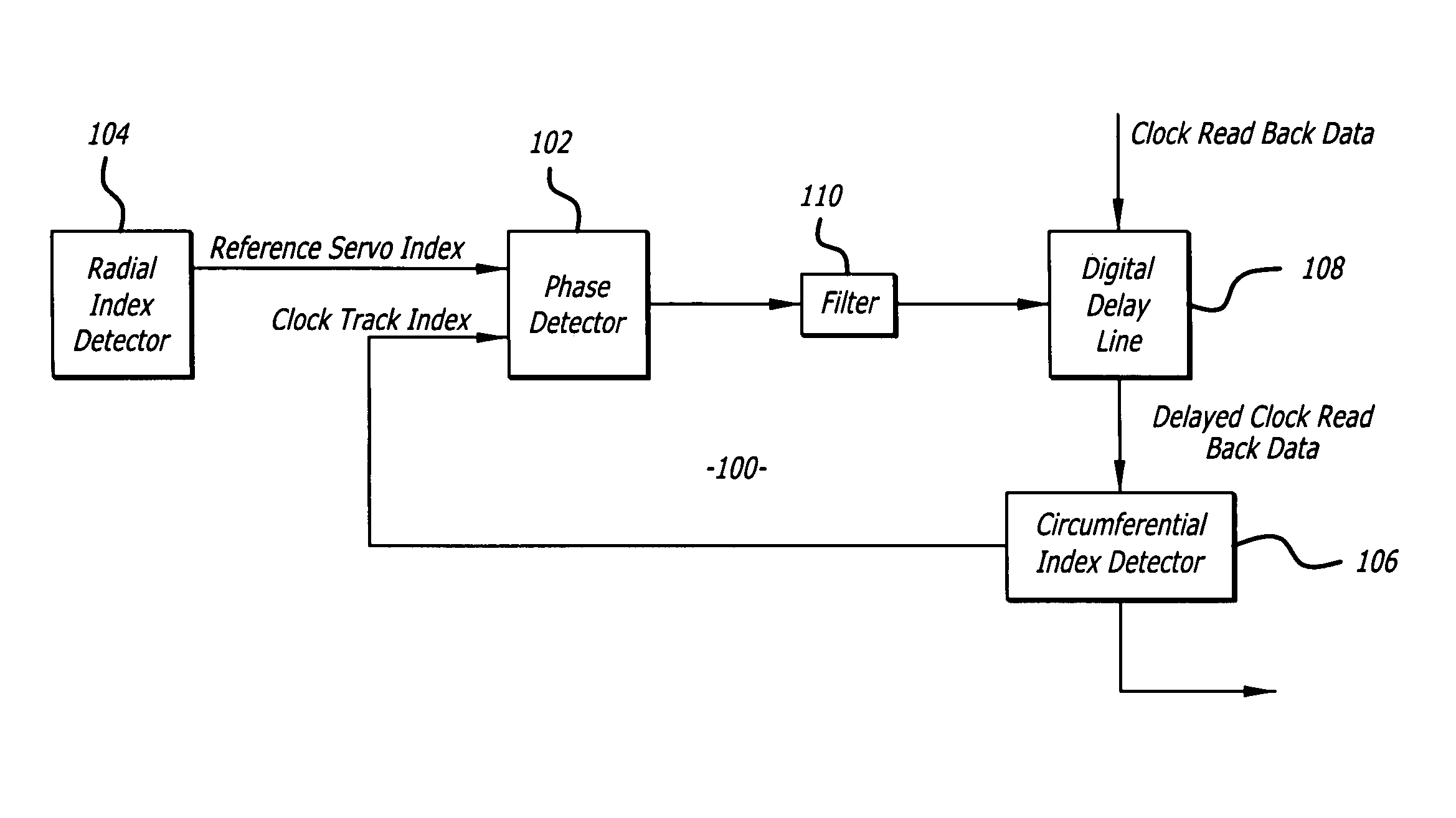
[0022]Disclosed is a method for writing servo information onto a disk of a hard disk drive with a servo writer. The disk has a circumferential index and a band of servo reference tracks. The circumferential index is detected from a clock signal generated from a clock track of the disk. The reference tracks include radial indices. A spiral servo pattern is written upon the detection of the circumferential index and a radial index. The servo writer includes a phase detector that detects changes in the relative position of the circumferential and radial indices and a delay circuit that delays the clock signal to offset such changes. The phase detector and delay circuit compensate for movement of the indices due to thermal expansion of the disk.

[0023]Referring to the drawings more particularly by reference numbers, FIG. 3 shows an embodiment of a hard disk drive 10 of the present invention. The disk drive 10 may include one or more magnetic disks 12 that are rotated by a spindle motor 1...


PUM

PropertyMeasurementUnit
phase detectoraaaaaaaaaa
phase differenceaaaaaaaaaa
magnetic fieldsaaaaaaaaaa

Abstract

A method for writing servo information onto a disk of a hard disk drive with a servo writer. The disk has a circumferential index and a band of servo reference tracks. The circumferential index is detected from a clock signal generated from a clock track of the disk. The reference tracks include radial indices. A spiral servo pattern is written upon the detection of the circumferential index and a radial index. The servo writer includes a phase detector that detects changes in the relative position of the circumferential and radial indices and a delay circuit that delays the clock signal to offset such changes.

Description

BACKGROUND OF THE INVENTION[0001]1. Field of the Invention[0002]The present invention relates to a method for writing servo onto disks of a hard disk drive.[0003]2. Background Information[0004]Hard disk drives contain a plurality of magnetic heads that are coupled to rotating disks. The heads write and read information by magnetizing and sensing the magnetic fields of the disk surfaces. Each head is attached to a flexure arm to create a subassembly commonly referred to as a head gimbal assembly (“HGA”). The HGA's are suspended from an actuator arm. The actuator arm has a voice coil motor that can move the heads across the surfaces of the disks.[0005]Information is typically stored on radial tracks that extend across the surface of each disk. Each track is typically divided into a number of segments or sectors. The voice coil motor and actuator arm can move the heads to different tracks of the disks.[0006]FIG. 1 shows a typical track that has a number of fields associated with each s...

Claims


Application Information

Patent Timeline
Patent Type & Authority Patents(United States)
IPC IPC(8): G11B21/02G11B5/09G11B5/596
CPCG11B5/59661G11B5/59688G11B21/10G11B20/10G11B5/02G11B5/596
Inventor GAMI, BIPINCHANDRA V.BRAGG, JOEIVANOV, NIKOLAYNGUYEN, LINHCHAN, KWONG TAT
Owner SAMSUNG ELECTRONICS CO LTD
Why Eureka
Try Eureka