Routing coordination protocol for a massively parallel router architecture

a router and routing coordination technology, applied in the field of massively parallel routers, can solve the problem of an expensive exchange of lsa packets in the flood scheme, and achieve the effect of reducing traffic and reducing routing traffi

Inactive Publication Date: 2007-08-07
SAMSUNG ELECTRONICS CO LTD
View PDF8 Cites 13 Cited by
  • Summary
  • Abstract
  • Description
  • Claims
  • Application Information

AI Technical Summary

Benefits of technology

[0016]A loosely-coupled unified environment (LUE) routing coordination protocol according to the principles of the present invention is designed to reduce the traffic among routing nodes (RNs) in a virtual area in which heavy traffic might result. The present invention proposes several unique improvements as follows. An Open Shortest Path First (OSPF) intra-domain routing protocol allows collections of contiguous networks and hosts to be grouped together. Such a group, together with the distributed routing archi...

Problems solved by technology

A flooding scheme is an expen...

Method used


Image

  • Routing coordination protocol for a massively parallel router architecture
  • Routing coordination protocol for a massively parallel router architecture
  • Routing coordination protocol for a massively parallel router architecture

Examples


Embodiment Construction

[0036]FIGS. 2 through 7, discussed below, and the various embodiments used to describe the principles of the present invention in this patent document are by way of illustration only and should not be construed in any way to limit the scope of the invention. Those skilled in the art will understand that the principles of the present invention may be implemented in any suitably arranged parallel router.

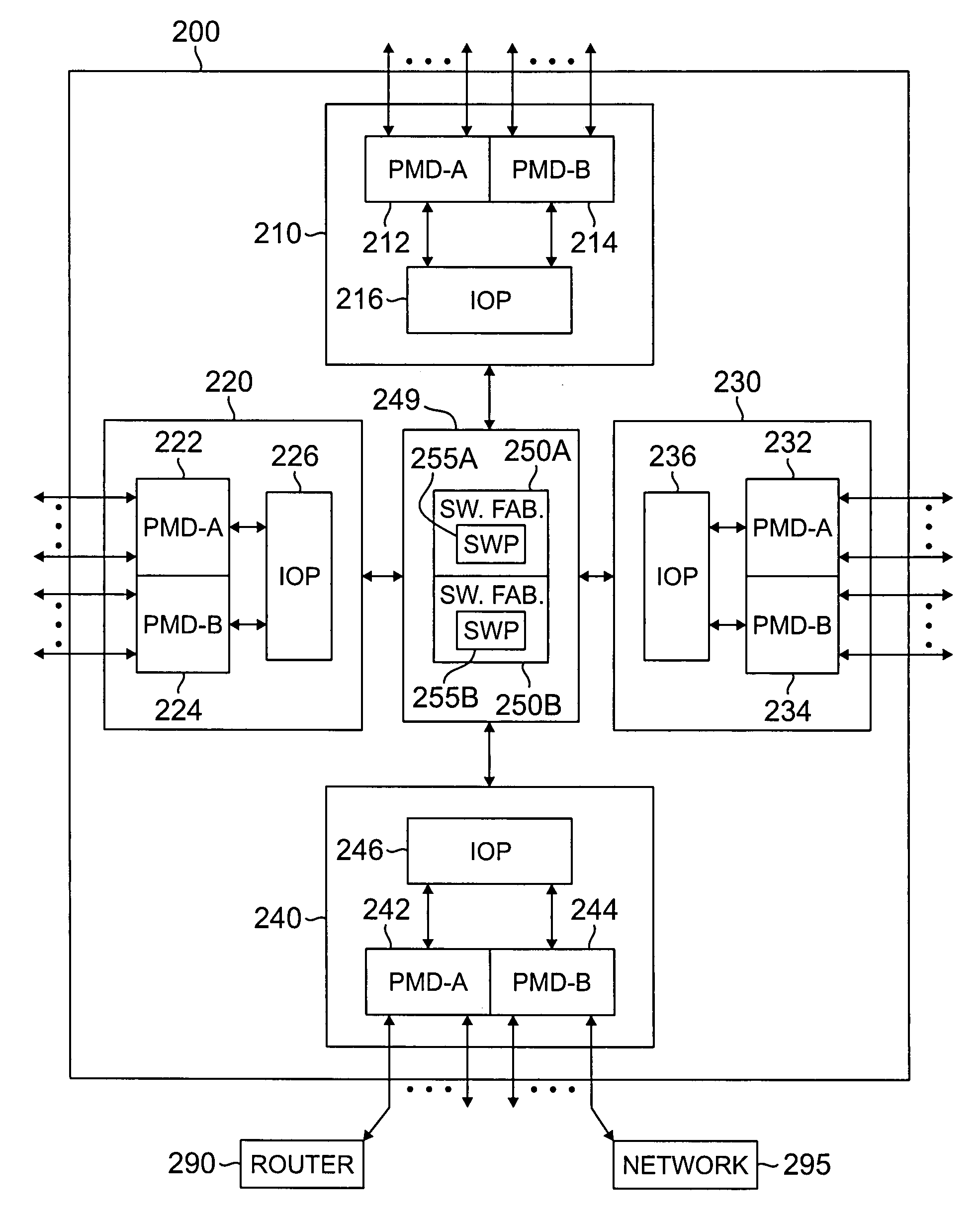
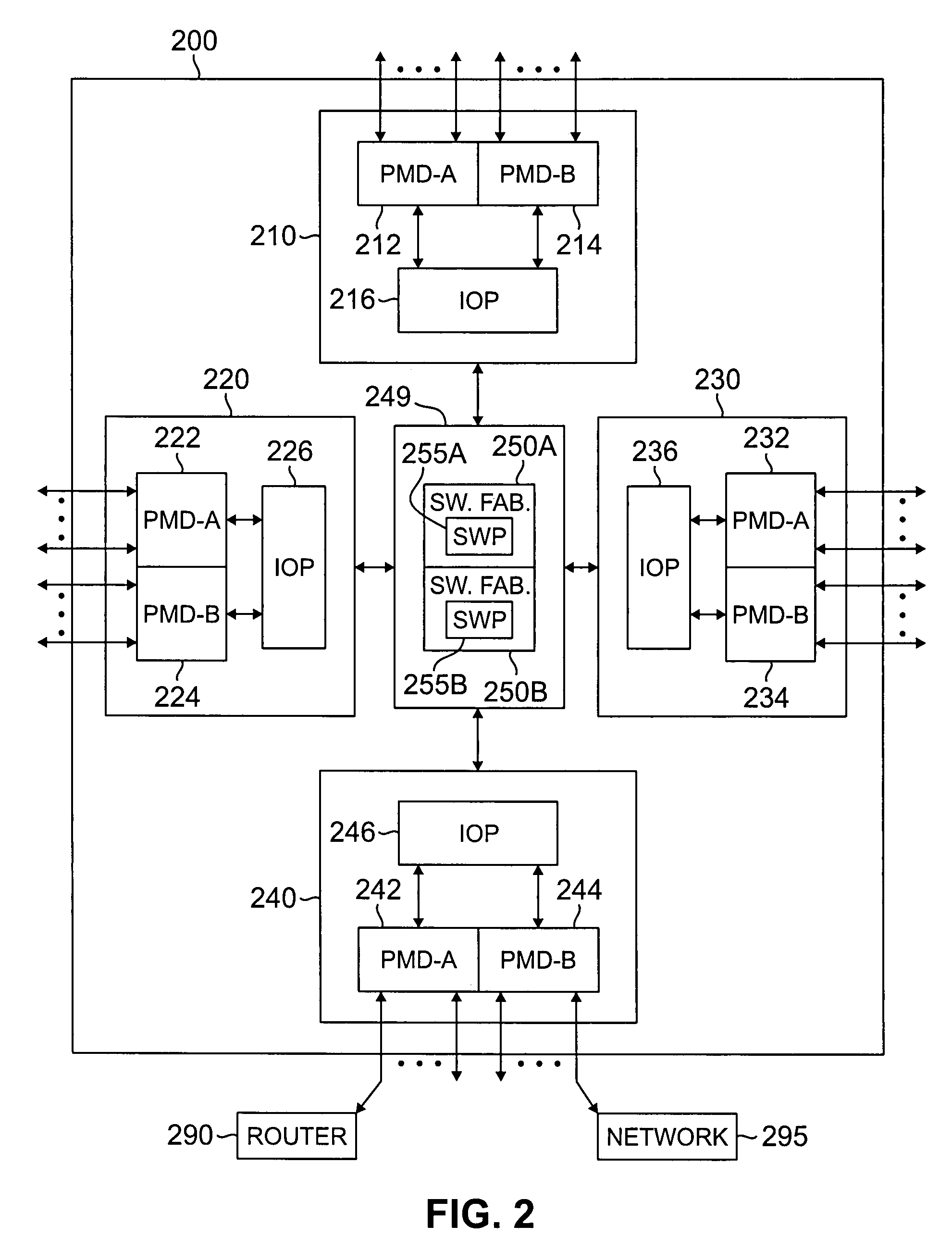
[0037]FIG. 2 illustrates parallel router architecture 200, which uses an improved routing coordination protocol according to the principles of the present invention. Parallel router architecture 200 provides scalability and high-performance using up to N independent routing nodes (RN), including exemplary routing nodes 210, 220, 230 and 240, connected by switch 249, which comprises a pair of high-speed switch fabrics 250A and 250B. Each routing node comprises an input-output processor (IOP), and one or more physical medium devices (PMDs). Exemplary RN 210 comprises PMD 212 (labeled PMD...


PUM


Abstract

A parallel router comprising: 1) a plurality of routing nodes, each of the plurality of routing nodes capable of receiving message packets from and transmitting message packets to external devices, wherein each of the routing nodes maintains a routing table suitable for routing message packets from transmitting ones of the plurality of routing nodes to receiving ones of the plurality of routing nodes; and 2) a switch fabric capable of transmitting the messages packets between the transmitting nodes and the receiving nodes, wherein a designated one of the plurality of routing nodes is operable to receive from non-designated ones of the plurality of routing nodes link state advertisement (LSA) message packets containing link state information, wherein the designated routing node aggregates the LSA message packets to thereby form a link-state database.

Description

CROSS-REFERENCE TO RELATED APPLICATIONS[0001]The present invention claims priority to U.S. Provisional Application Ser. No. 60 / 327,494, which was filed on Oct. 5, 2001, and to U.S. Provisional Application Ser. No. 60 / 327,230, which was filed on Oct. 5, 2001.[0002]The present invention is related to those disclosed in the following U.S. Patent Applications:[0003]1) Provisional Patent Application Ser. No. 60 / 327,494, filed Oct. 5, 2001, entitled “COORDINATION PROTOCOL FOR LOOSELY COUPLED MASSIVELY PARALLEL ROUTER;”[0004]2) Provisional Patent Application Ser. No. 60 / 327,230, filed Oct. 5, 2001, entitled “REDUNDANCY MECHANIZATION PROTOCOL FOR A MULTI-GIGABIT SWITCHING ROUTER;” and[0005]3) Patent application Ser. No. 10 / 193,355, filed concurrently herewith, entitled “REDUNDANCY MECHANIZATION PROTOCOL FOR A MASSIVELY PARALLEL ROUTER.”[0006]The above applications are commonly assigned to the assignee of the present invention. The disclosures of these related patent applications are hereby ...

Claims


Application Information

Patent Timeline
IPC IPC(8): H04J1/16H04L12/28H04L12/66H04L12/56H04L69/40
CPCH04L45/02H04L45/06H04L45/28H04L45/42H04L45/52H04L45/54H04L45/58H04L45/60H04L69/40H04L45/03
Inventor CHOE, MYONGSUWYBENGA, JACK C.SAMUDRA, PRADEEP
Owner SAMSUNG ELECTRONICS CO LTD
Why Eureka
Try Eureka