Method and apparatus for testing pulsatile endurance of a vascular implant

Inactive Publication Date: 2007-08-14
ANSON MEDICAL LTD
View PDF20 Cites 22 Cited by
  • Summary
  • Abstract
  • Description
  • Claims
  • Application Information

AI Technical Summary

Benefits of technology

[0015]The present invention relates to an improved arrangement for testing vascu

Problems solved by technology

None of these methods would be suitable for the pulsatile testing of a vascular implant.
There are a number of common failures or difficulties associated with locating the implant within a tube.
The most serious commercially is the consequence of a tube rupturing during the test.
The implant is first crushed before passing through the catheter and this crushing process can severely affect the life expectancy of the implant.
Thus, if the tube fails during a test, the tube itself can be replaced but it is not feasible to re-deliver the implant through a catheter.
However, endurance tests typically last between 3 and 6 months and such a failure can easily delay testing, and therefore the time to launch a product, by several months.
As a consequence of the above failure mode, designers of test machines will usually empl

Method used


Image

  • Method and apparatus for testing pulsatile endurance of a vascular implant
  • Method and apparatus for testing pulsatile endurance of a vascular implant

Examples


Embodiment Construction

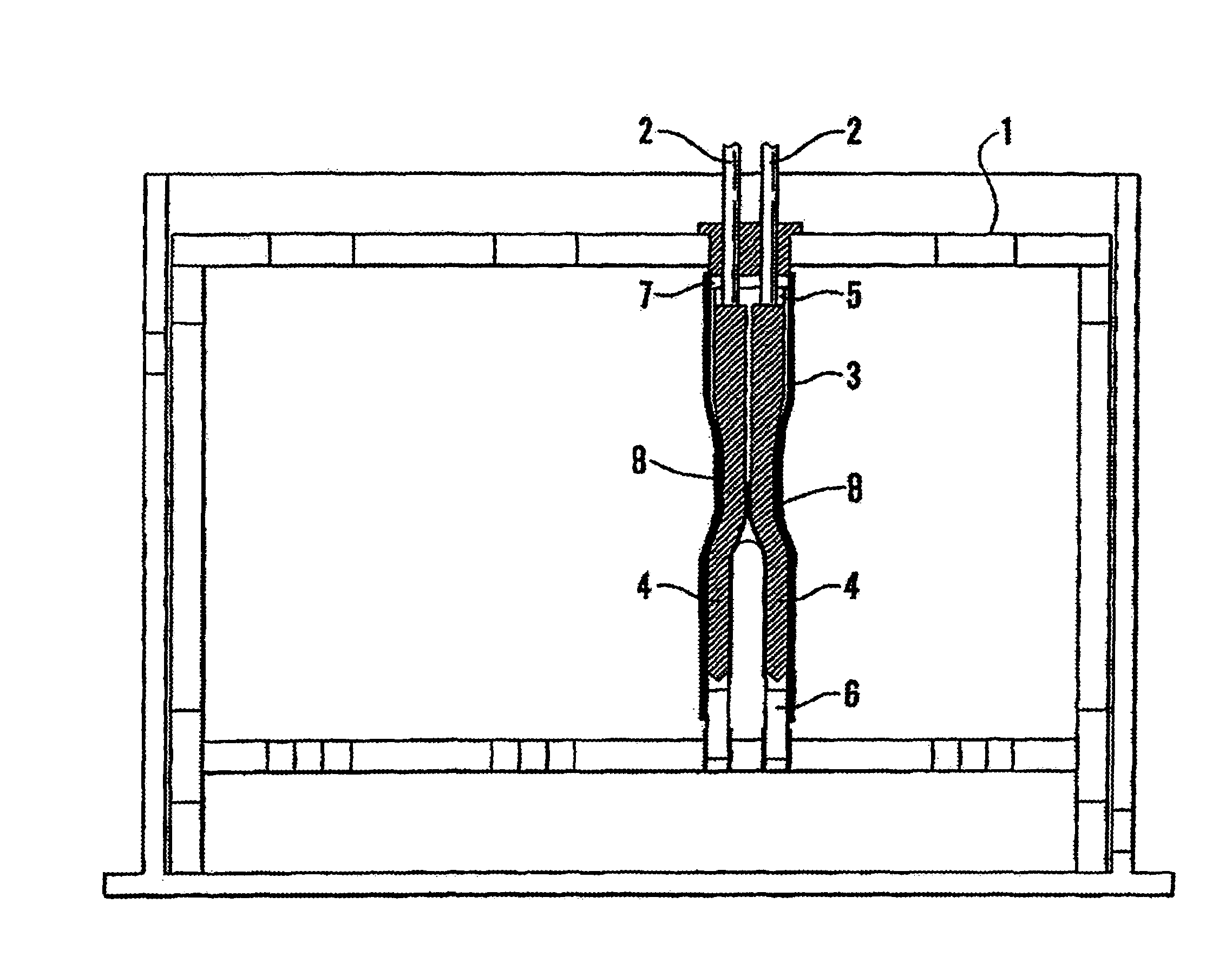
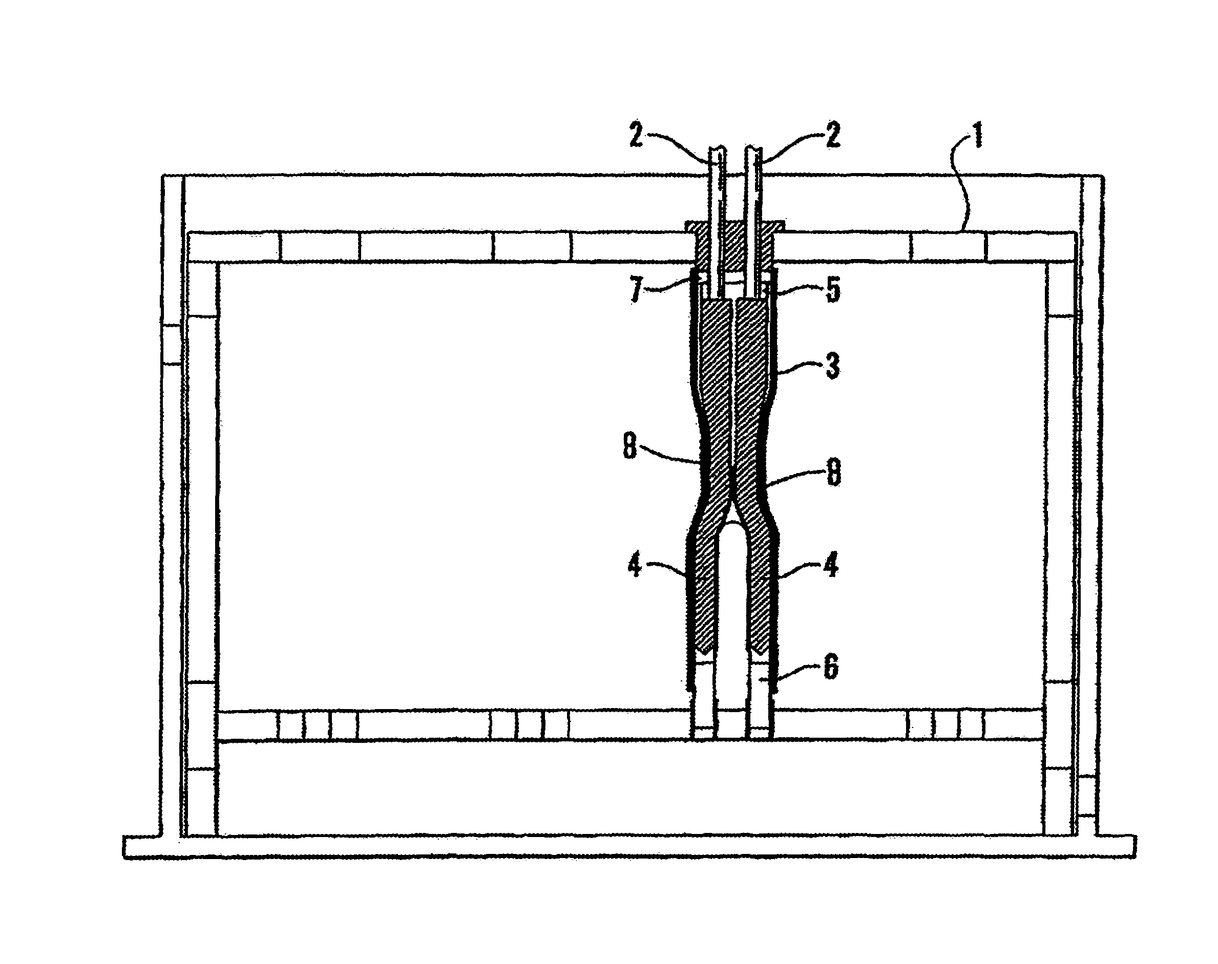
[0029]The apparatus of FIG. 1 comprises:[0030]A supporting gantry (1).[0031]Inlet tubes (2).[0032]Vascular implant (3).[0033]Inner tubes (4).[0034]Short outer tube to reduce compliance at the neck of the implant (5).[0035]Bungs (6) and (7).[0036]Outer sheath (8).

[0037]This arrangement employs ultra-thinwalled condoms as inner tubes (4) used as apairto fill the single main body of the implant (3) and its twin legs. In order to allow higher pressures to be used within the tubes (4), bungs (6) and (7) are used to limit the extent to which each tube can expand length-wise. At each exit to the vascular implant (3), this limit is arranged to lie within a portion of outer tube which runs continuously to the vascular implant. In this way, there is no path for the inner tube to expand or herniate beyond the vascular sample or outside the outer tube. This limits the ultimate strain put on the inner tubes and prevents it from bursting unless very high pressures are employed. Additionally, to p...


PUM


Abstract

A method for testing the pulsatile endurance of a vascular implant 3 comprises placing a resilient insert 4 into the implant and repeatedly expanding and contracting the insert, thereby expanding and contracting the implant. The insert preferably has a cavity therein and is repeatedly expanded and contracted by repeatedly increasing and decreasing the pressure in the cavity.

Description

FIELD OF THE INVENTION[0001]The present invention relates to a method and apparatus for testing pulsatile endurance of a vascular implant.BACKGROUND OF THE INVENTION[0002]Prosthetic vascular implants, such as heart-valves, stents, grafts and stent-grafts used for human implantation are subjected to the continuous fluctuating stress of blood pressure. It is therefore necessary to test such implants to prove their durability over a lifetime of exposure to pulsatile blood pressure.[0003]A number of prior art documents disclose destructive methods of testing non-resilient vessels (such as glass bottles) by inserting a resilient insert such as a bladder into the vessel and subjecting the bladder to extremely high expansive pressure to see if the vessel breaks (see for example U.S. Pat. No. 3,895,514; GB 2,177,220; GB 1,531,557; and GB 2,149,126). None of these methods would be suitable for the pulsatile testing of a vascular implant.[0004]Commercial machines for pulsatile testing of vasc...

Claims


Application Information

Patent Timeline
IPC IPC(8): G01N3/36G01N3/56A61F2/06A61F2/24
CPCA61F2/06A61F2/2472Y10S623/913Y10S623/912
Inventor KEEBLE, DUNCAN ROBERT
Owner ANSON MEDICAL LTD
Why Eureka
Try Eureka