Variable aperture velocity augmented ducted fan wind turbine

a ducted fan and variable aperture technology, applied in the direction of machines/engines, sustainable buildings, electric generator control, etc., can solve the problems of increasing the apparentity of the problem, increasing the cost of complete electrical utility infrastructure, and generating electrical power expensively shipped via high tension lines to the eventual power consumers, so as to enhance the flow of wind stream, improve safety and efficiency, and enhance the effect of stream flow over buildings

Inactive Publication Date: 2007-08-14
MARQUISS WIND POWER
View PDF12 Cites 49 Cited by
  • Summary
  • Abstract
  • Description
  • Claims
  • Application Information

AI Technical Summary

Benefits of technology

[0009]The instant invention is distinguished over the known prior art in many different ways. One of the most evident, and plainest differences that the instant invention employs over the known prior art is that the adjustable duct side walls, that is the planar characteristic, and angular disposition of the walls of the duct are configurable and adjustable, meaning that the ratio between the cross-sectional intake areas of the input, and the cross sectional area of the output sides of the duct can be precisely matched in aerodynamic efficiency and electrical power output to the input air mass.
[0015]Accordingly, it is a primary objective of the present invention to provide an aerodynamically configurable, ‘can be automatically, intelligently, computer controlled and optimized’ new and novel electrical power source to be utilized in conjunction with the windy rooftop locations on commercial and residential buildings and structures based upon enhanced wind stream flows created by those buildings themselves.
[0016]A further objective of the present invention is to provide a Ducted Fan Wind Turbine device more comparatively quiet, vibration free and thus safer and more efficient than any presently available ducted fan wind turbines, or open fan wind turbines designed for use in conjunction with or without enhanced stream flows over buildings.
[0017]Viewed from a first vantage point, it is an objective of the present invention to provide an aerodynamically configurable and automatically steering wind turbine device as characterized above which can be strategically placed on the rooftops of commercial and residential buildings in such a way that the building structure itself directs additional air mass and velocity flow into the intake aperture of the DFWT for the purpose of increasing the electrical output power of the wind turbine.
[0018]Viewed from a second vantage point, it is an objective of the present invention to provide a DFWT device for roof top building mounting which can be completely shielded from the exterior of the housing itself in the event of a fan failure, and which can be completely shielded from the intake and exhaust for the purpose of preventing bird or other object intake into the interior fan housing, and the fan itself of the DFWT. Further, the DFWT is completely balanced and the housing so designed as to prevent noise generation and vibration from being coupled into the architecturally attached building.
[0019]Viewed from a third vantage point, it is an objective of the present invention to provide a wind turbine device which may be coupled directly into the mounted building electrical structure for the purpose of maximally efficient electrical power transfer into the building load.

Problems solved by technology

However, modern large open fan wind turbines have certain characteristics and problems in the process of becoming more apparent as the installation base of such turbines increases,
Thus the wind turbine installations must be accompanied by expensive, complete electrical utility infrastructures, and the generated electrical power expensively shipped via high tension lines to the eventual power consumers.
In European countries, such as England, having high quality wind resources, and a large installed large open fan wind turbine base, the location of very visible open fan wind turbines is interfering with aesthetic sight line values concerning tourists.

Method used


Image

  • Variable aperture velocity augmented ducted fan wind turbine
  • Variable aperture velocity augmented ducted fan wind turbine
  • Variable aperture velocity augmented ducted fan wind turbine

Examples


Embodiment Construction

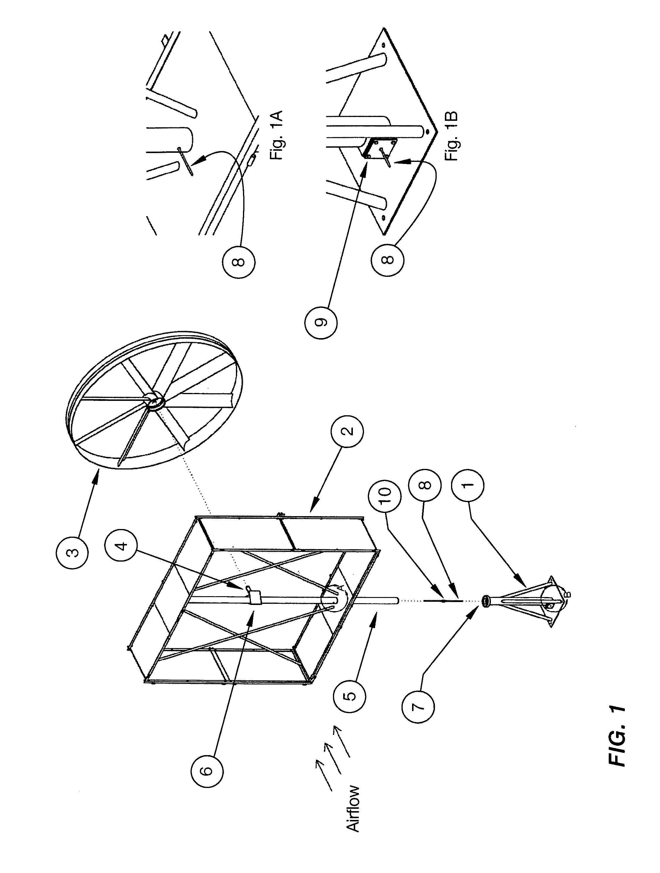
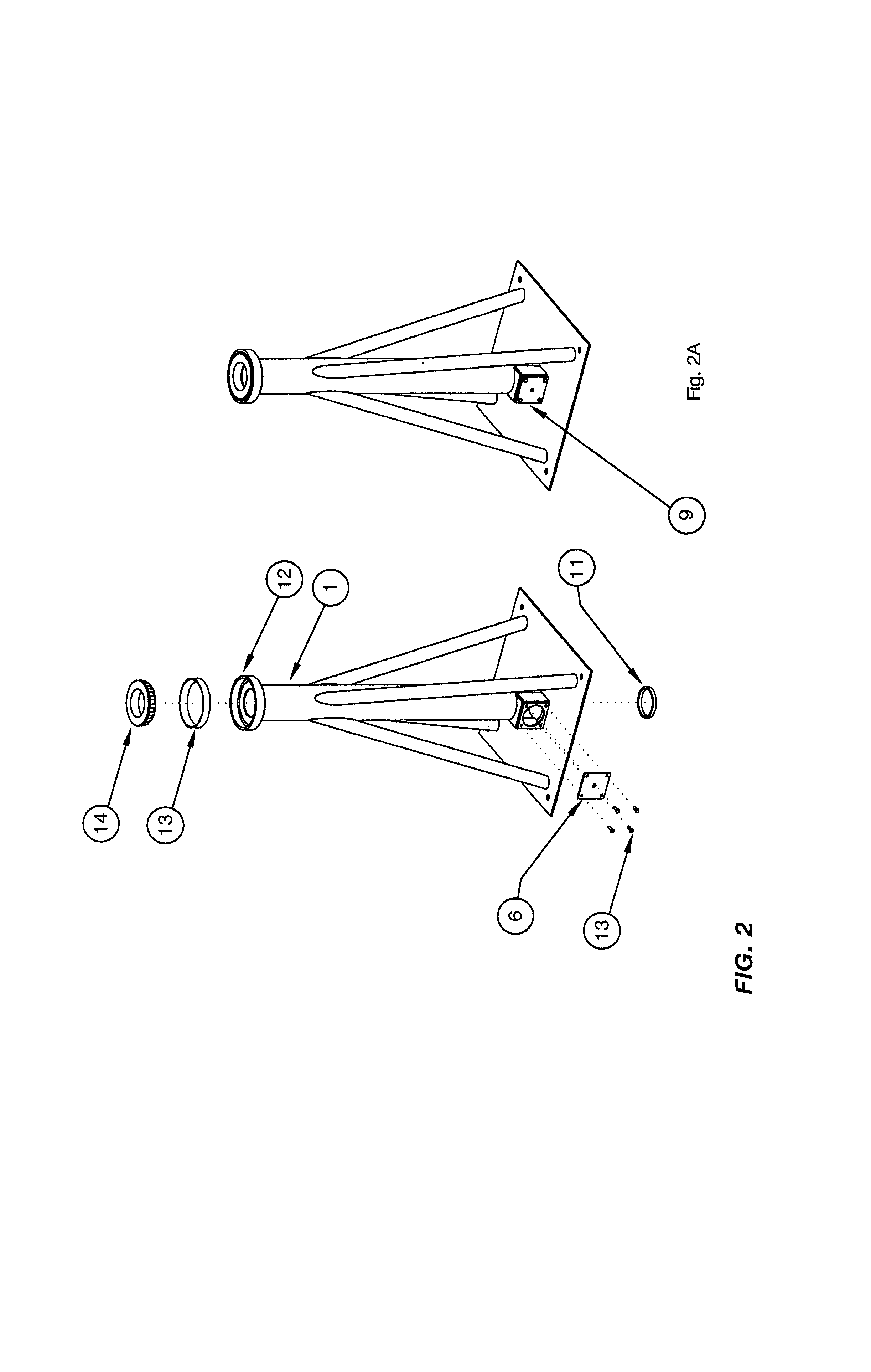
[0046]Considering the drawings, wherein like reference numbers denote like parts throughout the various drawing figures, reference numeral 1 is directed to the foundation base of the center fan power cell of the DFWT according to the present invention.

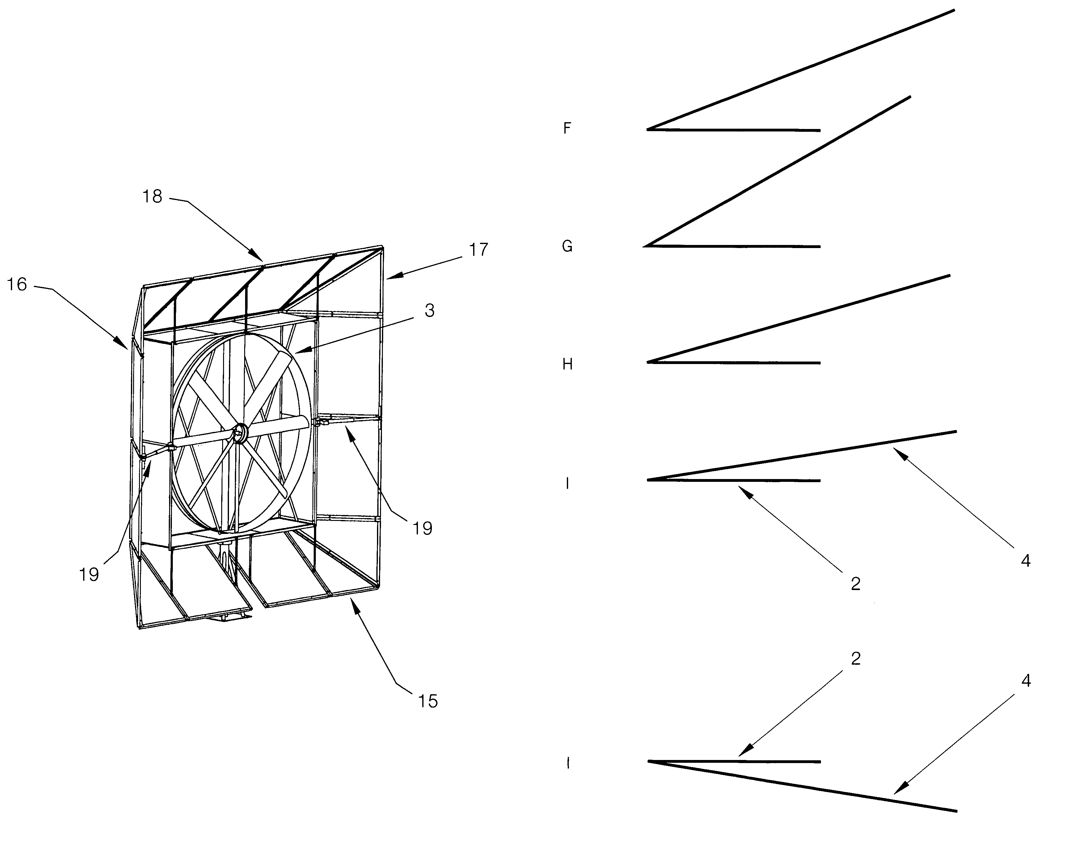
[0047]In essence, and with respect to FIG. 1, the center fan power cell assembly itself is denoted by the numeral 2, with the turbine fan assembly itself, denoted by the numeral 3, to be attached to the welded hub spindle, denoted by the numeral 4, welded to the center cell power pipe mast denoted by the numeral 5, around which the incoming air mass diverter, spinner equivalent V plate is denoted by the numeral 6. As can be seen in FIG. 1, the center cell pipe mast fits within the center pipe of the foundation base pipe, the open top aperture of which is denoted by the numeral 7. FIG. 1 also shows the generator 21, power output wire 8 traveling through the inner fan power cell mast pipe 5, and also through the mounting base assembly ou...


PUM


Abstract

A wind powered variable area exit aperture electric generating system having configurable, adjustable duct side walls by which means the ratio between the intake cross-sectional aperture area and the exhaust cross-sectional aperture area may be varied for maximum air molecule flow through the duct, leading to ideal maximum electrical output for any given air mass input. The planar characteristic and angular dispersion of the mutually leading edge coupled extended flaps, and the regular square interior housing result in complementary internal vortices developed at the trailing edge of the planar architectural surfaces.

Description

FIELD OF THE INVENTION[0001]This invention relates generally to a variable aperture and geometry ducted fan wind turbine which converges intake air masses allowing use on turbulence inducing, and air input flow increasing adjacent structures, such as commercial and residential buildings. The configurable duct also rapidly directs the turbine intake directly into the wind, while the full aerodynamic housing reduces vibration and noise while completely isolating and shielding the area outside the fan from any fan breakage, while also shielding the fan from objects, birds, and the like, at the intake and exhaust.BACKGROUND OF THE INVENTION[0002]For several thousand years wind turbines have been used as prime power movers in raising water or powering mills grinding grains. Just after the turn of the 19th Century into the 20th Century, before the First World War, perhaps a million open fan wind turbines were in use within the US alone, pumping water in farms and ranches all over America....

Claims


Application Information

Patent Timeline
Patent Type & Authority Patents(United States)
IPC IPC(8): F03D9/00F03B15/06F03D7/00F03D7/02H02P9/04
CPCF03D1/04F03D7/02F05B2240/13Y02B10/30Y02E10/723Y10S415/908F03D13/20F03D80/70Y02E10/72Y02E10/728
Inventor MARQUISS, STANLEY
Owner MARQUISS WIND POWER
Why Eureka
Try Eureka