Phase array oxide-confined VCSELs

a phase array and oxide-confined technology, applied in semiconductor lasers, laser details, electrical apparatus, etc., can solve the problems of limiting the light output power, single-mode devices with special shortcoming, and distinct spots that are unsuitable for communications and printing applications, and achieve enhanced mode coupling and high gain coupling

Inactive Publication Date: 2007-08-14
PALO ALTO RES CENT INC
View PDF65 Cites 56 Cited by
  • Summary
  • Abstract
  • Description
  • Claims
  • Application Information

AI Technical Summary

Problems solved by technology

However, the small light emission area of each VCSEL severely limits the light output power that can be generated and output by each VCSEL.
This shortcoming is especially severe in single mode devices.
These distinct spots are unsuitable for communications and printing applications where a central radiation lobe with a high concentration of power output is desired.

Method used


Image

  • Phase array oxide-confined VCSELs
  • Phase array oxide-confined VCSELs
  • Phase array oxide-confined VCSELs

Examples


Embodiment Construction

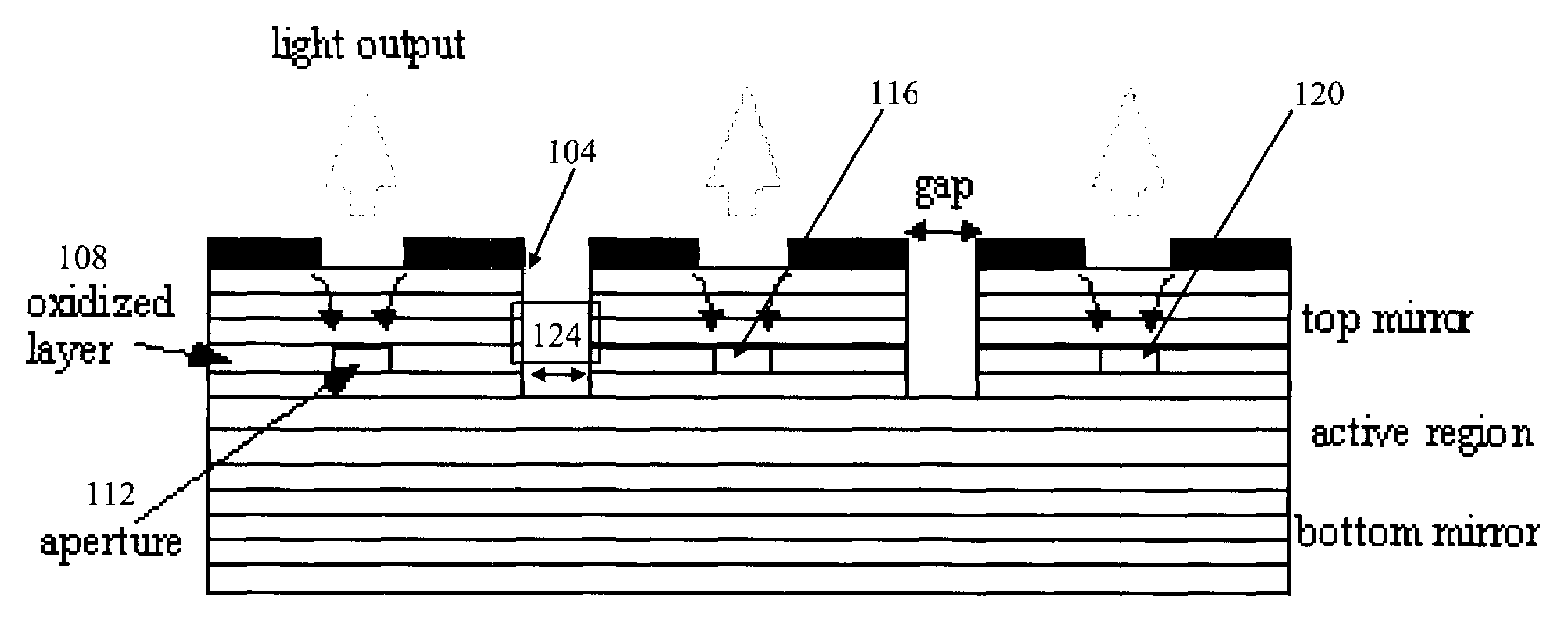
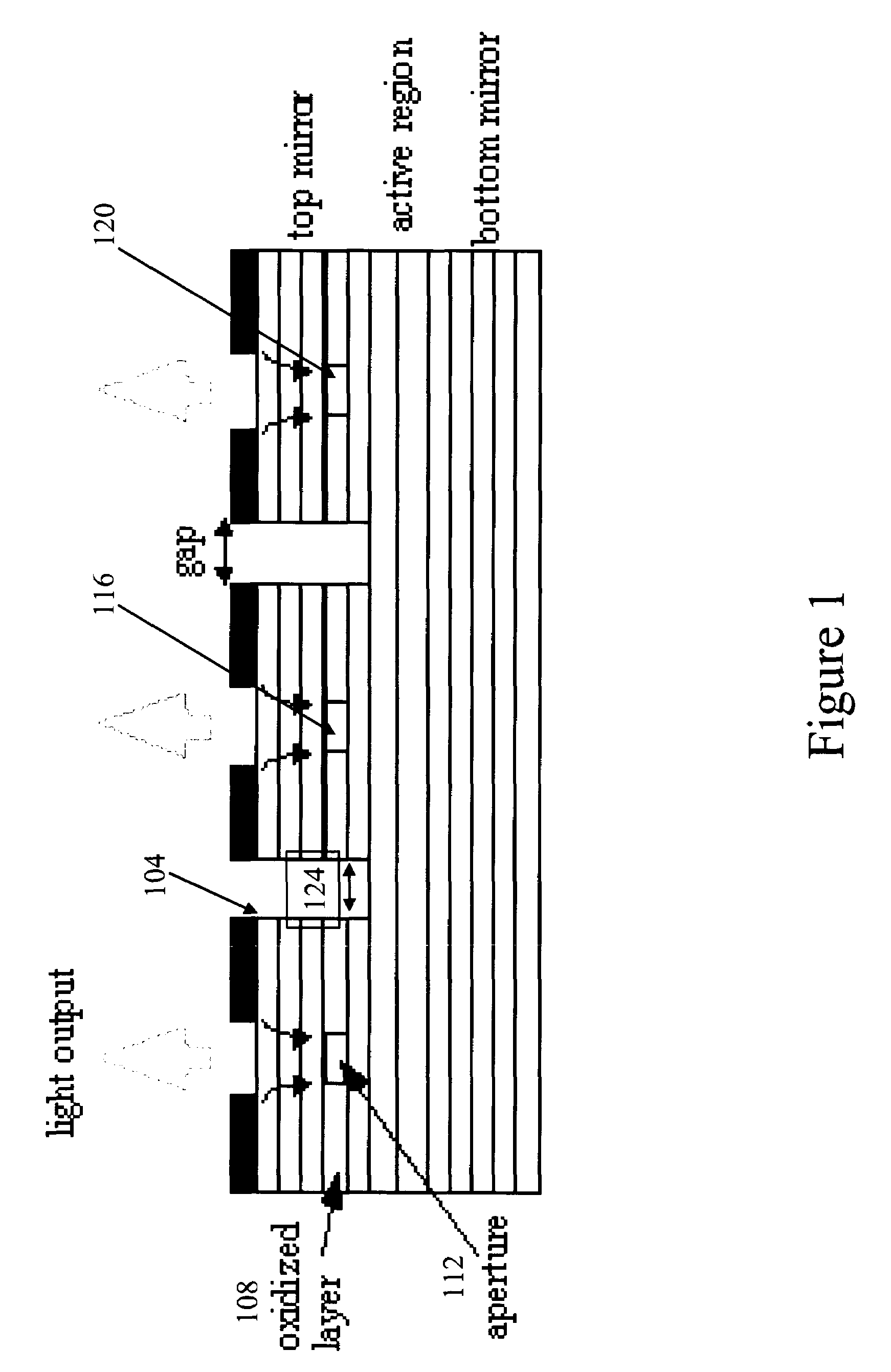
[0014]In the following detailed description, a method and system of forming an array of VCSELs using laterally oxidized apertures will be described. A common contact addresses several VCSELs simultaneously. In one embodiment of the invention, the VCSELs will be closely spaced and separated by thin, laterally oxidized regions designed to promote mode leakage between adjacent VCSELs. The mode leakage keeps the output of adjacent VCSELs in phase thereby allowing the output of these adjacent VCSELs to be combined into a coherent composite beam.

[0015]FIG. 1 shows a cross-sectional side view of an oxide-confined VCSEL mesa-structure with an etched pillar structure. Mesa sidewalls 104 provide access to buried aluminum-containing layers 108. Buried layer 108 is selectively oxidized to form laser apertures 112, 116, 120. In typical prior art VCSELs, the edge of the mesa completely surrounds the laser aperture such that an air gap 124 completely separates adjacent laser apertures 112 and 116....


PUM


Abstract

A phase array of oxide confined VCSELs and a method for forming the phase array of oxide confined VCSELs is described. VCSELs in the array are designed to be simultaneously addressed such that the output of multiple VCSELs can be used to increase the light intensity at a point. In applications where beam coherence from the VCSEL array is desirable, high gain coupling regions break the continuity of the oxide wall surrounding each VCSEL aperture. The high gain coupling regions connect adjacent VCSELs in the VCSEL array thereby allowing mode coupling between adjacent lasers and the output of a coherent beam of light.

Description

BACKGROUND[0001]The relative ease with which vertical cavity surface-emitting lasers (VCSELs) can be fabricated has resulted in the increasing use of VCSELs in a variety of applications such as printing, data storage and network communications. However, the small light emission area of each VCSEL severely limits the light output power that can be generated and output by each VCSEL. This shortcoming is especially severe in single mode devices. The narrow beam profile of single mode devices is highly desirable in a range of applications ranging from printing to wide area network communications.[0002]One method of increasing the optic power at a target point is to align and simultaneously switch several lasers to form a composite beam. However, using an array of independent lasers results in each laser having its own independent intensity pattern. Combining independent intensity patterns results in a composite beam that appears as several distinct spots. These distinct spots are unsuit...

Claims


Application Information

Patent Timeline
Patent Type & Authority Patents(United States)
IPC IPC(8): H01S5/00H01L21/00H01S5/183H01S5/026H01S5/42
CPCH01S5/423H01S5/18313H01S5/18338
Inventor CHUA, CHRISTOPHER L.
Owner PALO ALTO RES CENT INC
Why Eureka
Try Eureka