Apparatus for inserting, retaining and extracting a device from a compartment

a technology for compartments and devices, applied in the direction of electrical apparatus casings/cabinets/drawers, coupling device connections, instruments, etc., can solve the problems of no industry standard presently exists for mounting such devices on the mechanical substructure, and the potential for substantial damage, so as to prevent the damage of electrical components from static electricity and low profile

Inactive Publication Date: 2007-08-21
SANDISK TECH LLC
View PDF10 Cites 17 Cited by
  • Summary
  • Abstract
  • Description
  • Claims
  • Application Information

AI Technical Summary

Benefits of technology

[0006]The present invention relates to guides mounted upon a mechanical substructure for engaging corresponding rails attached to a device to be demountably mounted upon the mechanical substructure. The alignment of the device with components of the mechanical substructure is assured through predetermined interconnection and alignment between the guides and the rails. Such alignment permits mating between electro-mechanical connectors attendant the device and the mechanical substructure. Elements interacting between the guides, mechanical substructure, and rails assure dissipation of any electrostatic charges and zero static potential upon mounting of the device to preclude damage to the electrical components from static electricity. The cooperative engagement between the guides and rails eliminates the need for manual access to make further mechanical or electrical connections and thereby permits a low profile mechanical packaging enclosure commensurate in size with the device to be mounted. The device is retained upon the structure by one ore more pivotable lockable handles that may be grasped to insert, lock, unlock and retract the device.
[0010]Yet another objective of the present invention is to provide a mounting assembly which eliminates the need for manual mechanical connection and manual engagement of mating electrical conductors.
[0013]A still further object of the present invention is to provide guides attachable to a front panel of a substructure, providing strength to the aligned guides, the substructure, and the device mounted on the guides.

Problems solved by technology

No industry standard presently exists for mounting such devices on the mechanical substructure.
Furthermore, the electrical interconnections vary widely in type and usually require manual engagement.
The potential for substantial damage due to static electricity to components mounted on the mechanical substructure or components of a device being mounted exists.
To dissipate any electrostatic charges, known procedures must be employed but the carrying out of such procedures is sometimes omitted with attendant actual or potential damage to one or more components.

Method used


Image

  • Apparatus for inserting, retaining and extracting a device from a compartment
  • Apparatus for inserting, retaining and extracting a device from a compartment
  • Apparatus for inserting, retaining and extracting a device from a compartment

Examples


Embodiment Construction

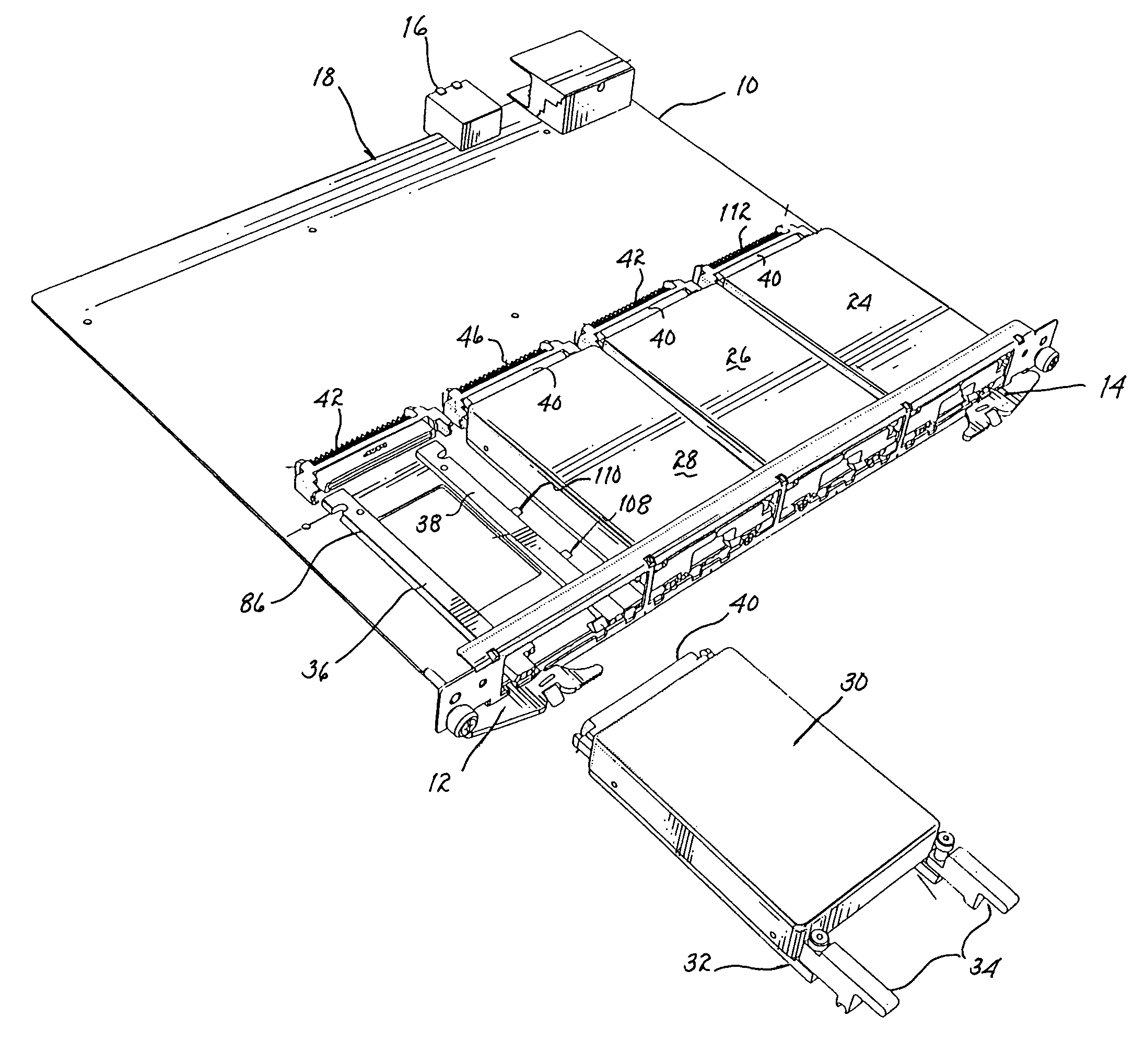
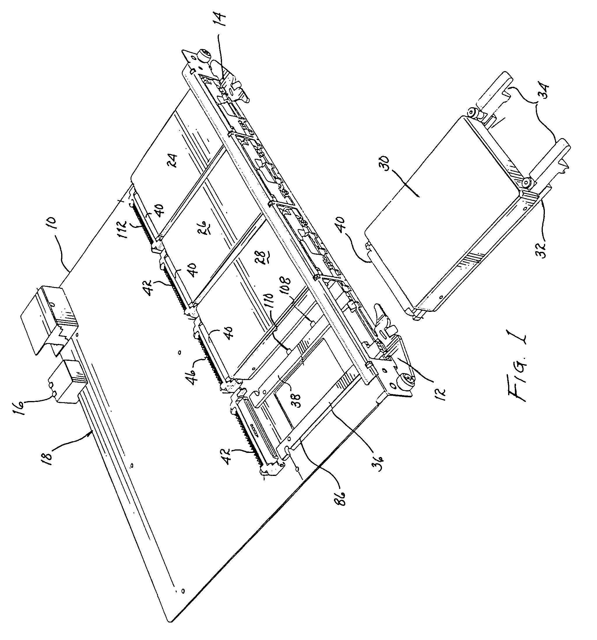
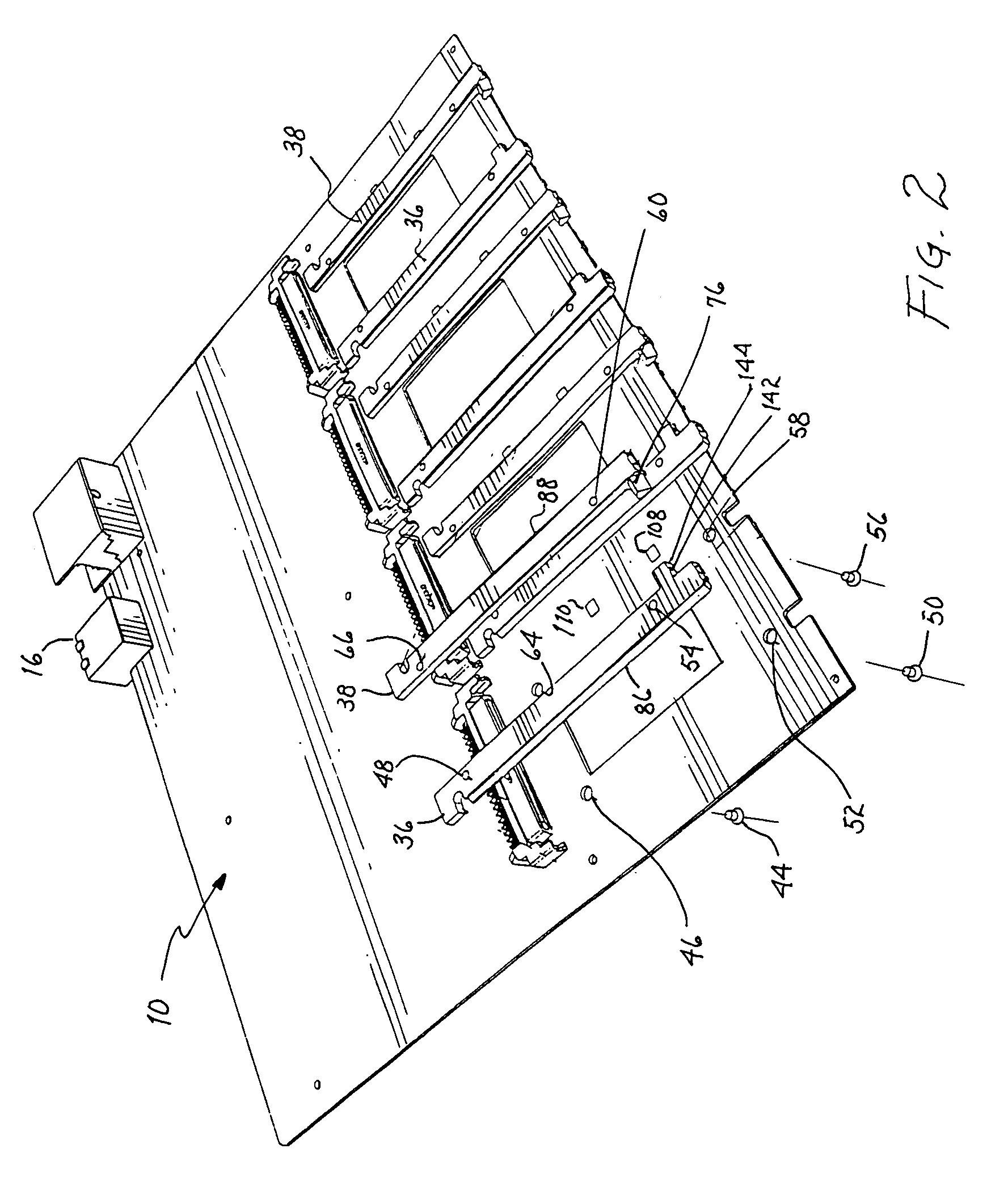
[0028]Referring to FIGS. 1 and 2 there is shown a mechanical substructure 10 used as a mounting for various electrical, electromechanical and mechanical elements. The substructure is typically removable from a chassis of a signal processing equipment. Generally, substructure 10 and the elements forming a part thereof will constitute a component of a unit (not shown) wherein signal processing is performed. The substructure may incorporate clasps 12 and 14 for detachably attaching a face plate to the substructure. Substructure 10 may also include various electromechanical connectors 16 disposed along rear edge 18 for electrically engaging other components of the signal processing equipment. Although not shown, various electrical components, such as integrated circuits, transistors, resistors, capacitors, inductors, microprocessors, etc. may be mounted on the substructure.

[0029]Electrico-mechanical devices, such as media storage devices, hard disk drives, etc., may be demountably mount...


PUM

PropertyMeasurementUnit
static chargeaaaaaaaaaa
sizeaaaaaaaaaa
electrostatic chargesaaaaaaaaaa

Abstract

Each of one or more devices to be detachably attached to a mechanical substructure includes rails on opposed sides with insertion / extraction mechanisms. Each of a plurality of pairs of guides mounted on the substructure slidably receives and retains a respective set of rails upon attachment of the devices. The insertion / extraction mechanism includes one or more pivotable handles associated with each device for retaining the device with the substructure. A spring extending from a rail makes electrical contact with electrostatic discharge ground pads on the substructure to discharge existing static charge from the device prior to electrical engagement between an electrical connector on the device and an electrical connector on the substructure. An apertured plate of the substructure includes a plurality of apertures through which the devices are inserted / extracted. A face plate may be hingedly attached to and removable from the apertured plate to cover all of the apertures therein that accommodate insertion / extraction of the devices.

Description

CROSS REFERENCE TO RELATED APPLICATIONS[0001]The present application is related to and claims priority to a provisional application entitled “Method and Apparatus for Inserting, Retaining and Extracting a Device from a Compartment”, filed Jan. 12, 2005, and assigned Ser. No. 60 / 643,524, which application describes an invention by the present inventors and is assigned to the present assignee.BACKGROUND OF THE INVENTION[0002]1. Field of the Invention[0003]The present invention relates to mating assemblies and, more particularly, to a guide assembly for mechanically supporting and electrically connecting a rail mounted device.[0004]2. Description of the Related Prior Art[0005]Various mechanical substructures, such as printed wiring boards and other mechanical devices provide support for detachably attached devices of various sorts that are electrically connected to elements attendant the mechanical substructure. No industry standard presently exists for mounting such devices on the mec...

Claims


Application Information

Patent Timeline
Patent Type & Authority Patents(United States)
IPC IPC(8): B23P19/00
CPCH05K7/1461Y10T29/49126Y10T29/5313Y10T29/53174Y10T29/53178Y10T29/49826
Inventor HAAGER, JAMES A.TUPA, RONALD E.FOGELSON, DANIEL P.
Owner SANDISK TECH LLC
Why Eureka
Try Eureka