Stepped dimming ballast for fluorescent lamps

a fluorescent lamp and ballast technology, applied in the direction of instruments, process and machine control, light sources, etc., can solve the problems of adverse effect on the life span of fluorescent lamps

Inactive Publication Date: 2007-08-21
MASS TECH (HK) LTD
View PDF5 Cites 61 Cited by
  • Summary
  • Abstract
  • Description
  • Claims
  • Application Information

AI Technical Summary

Benefits of technology

[0004]An object of the present invention is to eliminate the foregoing technical problems in the prior art by providing a stepped dimming ballast for fluorescent lamps, which is adapted for use in conjunction with a silicon controlled rectifier dimmer and / or a regular light switch thereby it is novel in structure and able to effect dimming in two predetermined and reliable operation modes.
[0015]According to the present invention, the multi-stepped dimming can be effected in two predetermined and reliable operation modes. One of which is by virtue of the alteration of the conduction angle of the silicon controlled rectifier dimmer or by means of the momentary switching of the regular light switch thereof. A valid alteration will be identified while the conduction angle of the SCR dimmer being varied from the maximum to a suitable level and then back to the initial value. Alternatively, a valid alteration will be identified while the ballast is switched off and on within a short duration by making use of the light switch.

Problems solved by technology

The characteristic suits the operation modes of a resistive load such as an incandescence lamp so well but being undesired by a capacitive load such as a fluorescent lamp for the reason that blinking might occur and a proper working state thereof might not be maintained in course of dimming while such dimmers are employed, which in turns has an adverse effect on the life span of the fluorescent lamp.

Method used


Image

  • Stepped dimming ballast for fluorescent lamps
  • Stepped dimming ballast for fluorescent lamps
  • Stepped dimming ballast for fluorescent lamps

Examples


Embodiment Construction

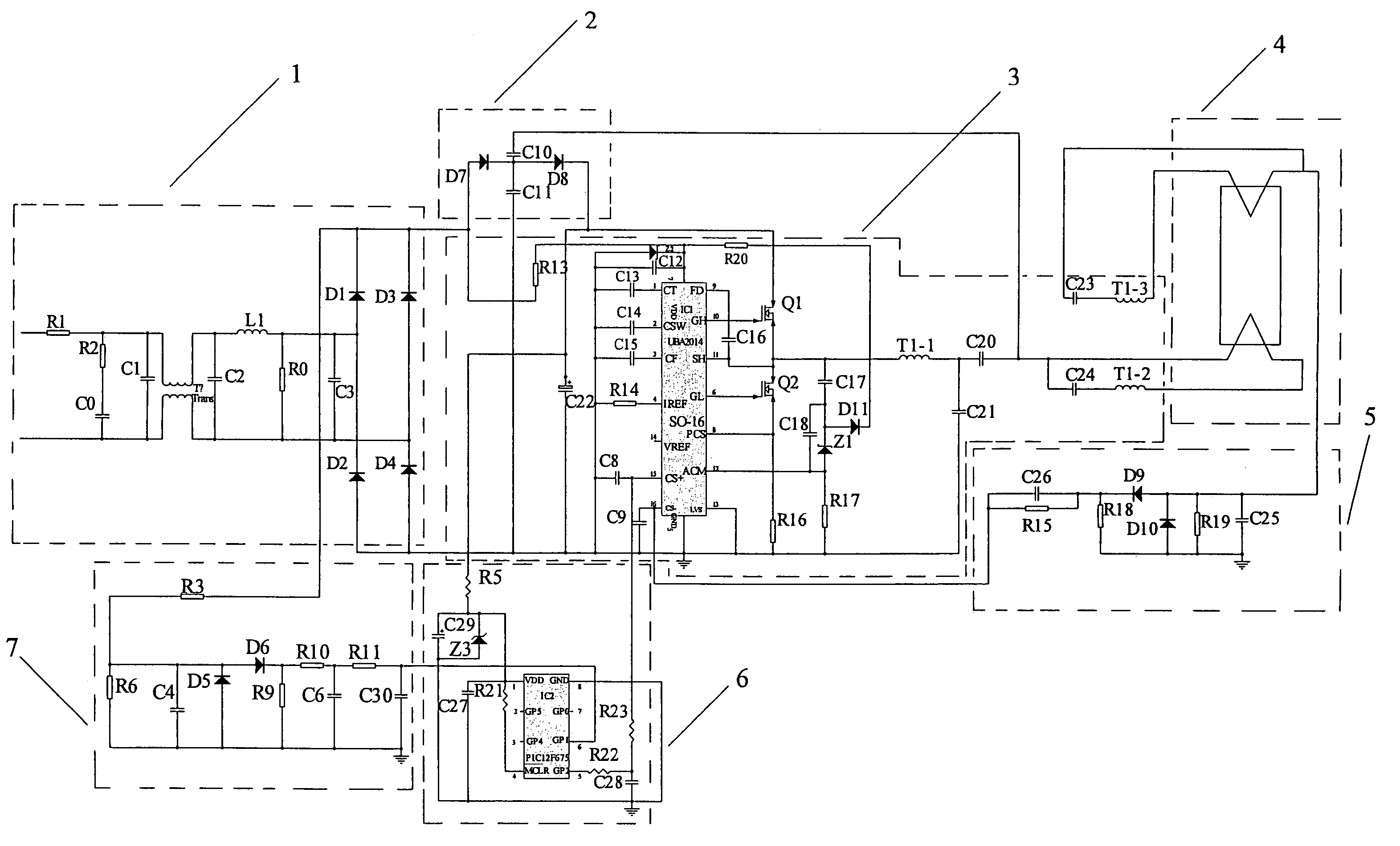
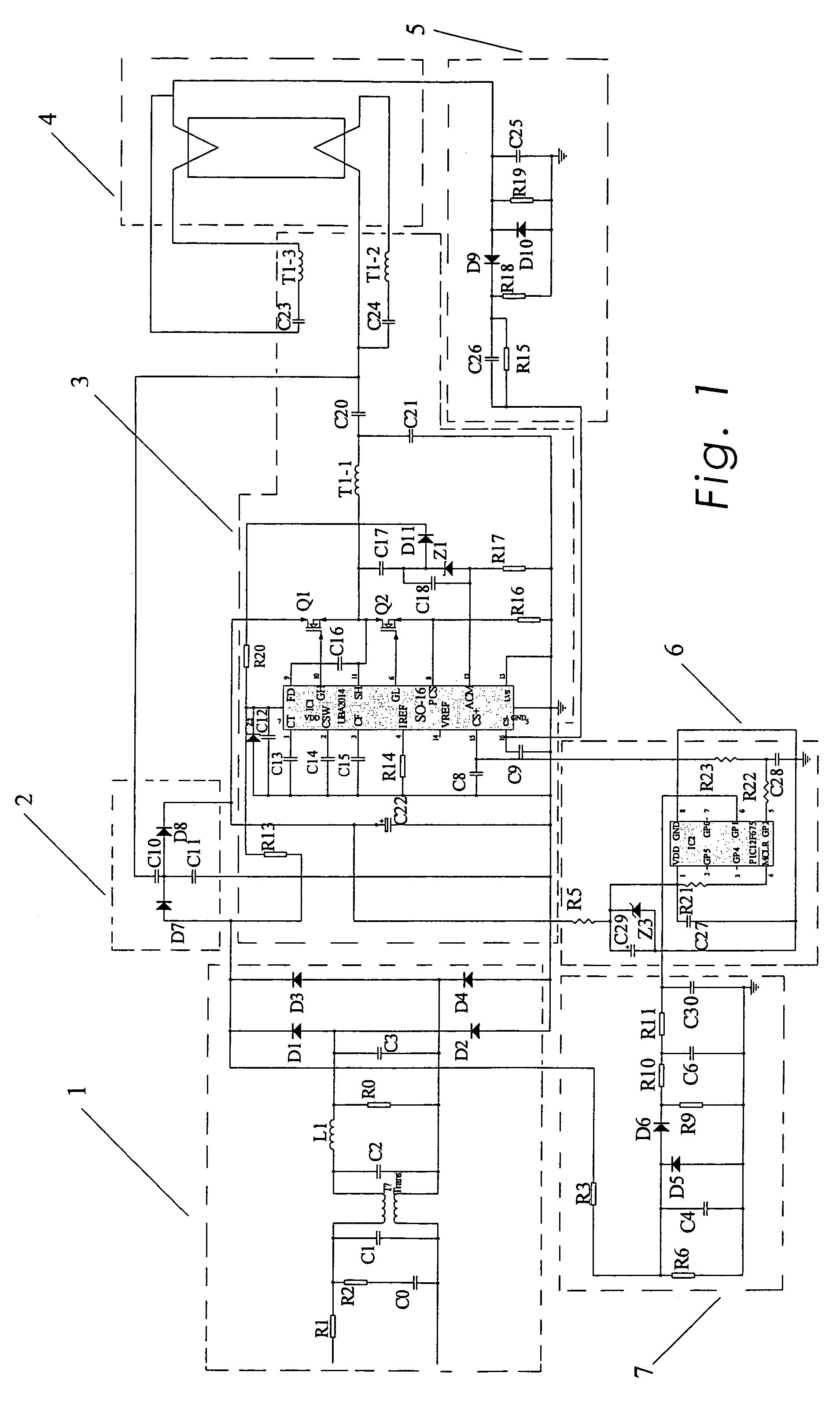
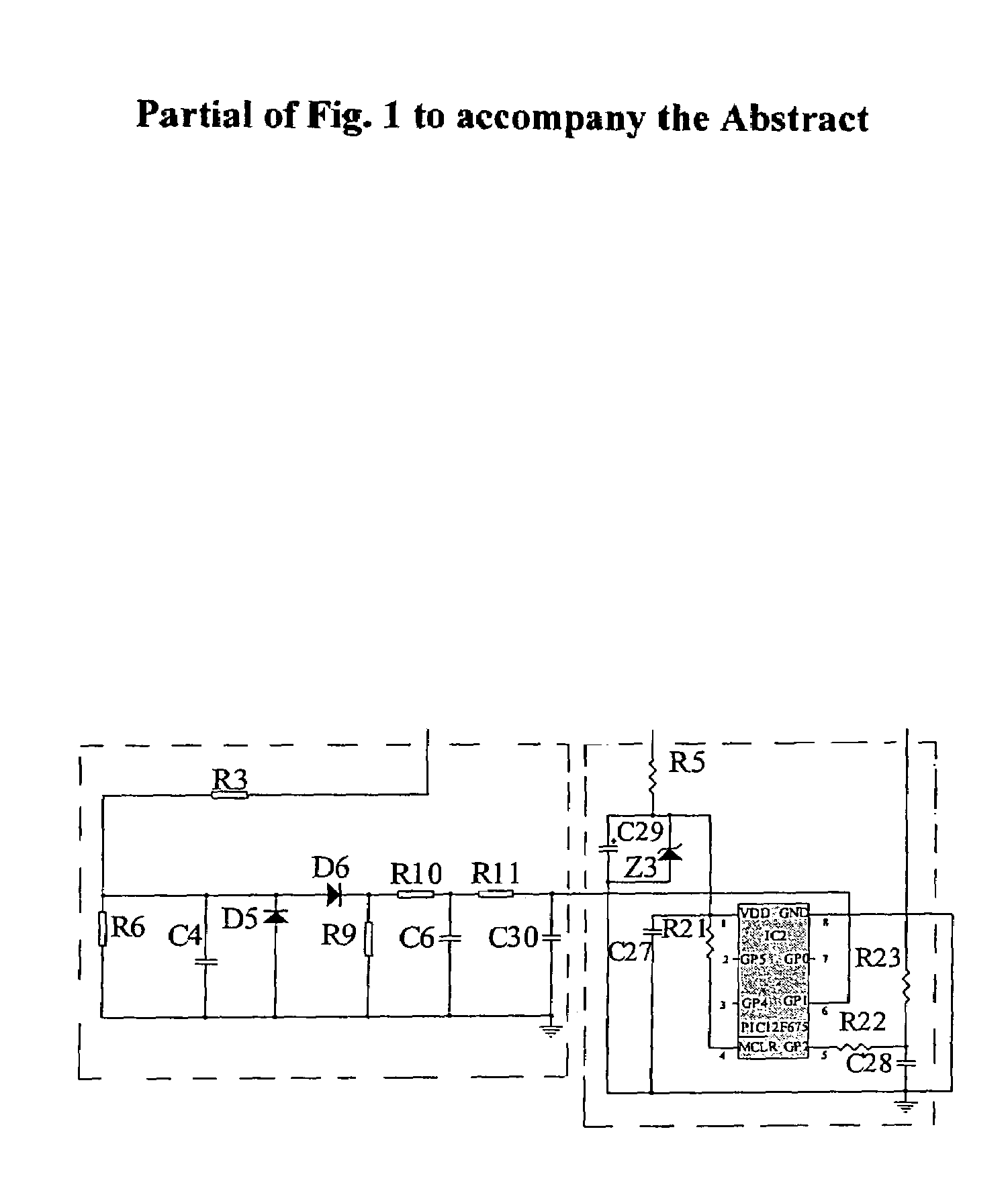
[0020]Referring to FIG. 1, a circuit diagram of a stepped dimming ballast for fluorescent lamps in accordance with the present invention is illustrated. The stepped dimming ballast comprises a filter and rectifier circuit 1, a DC high voltage stabilizing circuit 2, a frequency control and switch circuit 3, a load current feedback circuit 5, a voltage signal processing circuit 6 and a voltage signal sampling circuit 7. Wherein a lamp load 4 is coupled with the output end of the frequency control and switch circuit 3.

[0021]According to the embodiment, the filter and rectifier circuit 1 comprises, in series, a π filter, a LC filter, a RC filter and a bridge rectifier whereby to filter the high frequency interference waves from the coupled AC power source and converting the AC input voltage thereof into the DC ripple voltage.

[0022]The output end of the filter and rectifier circuit 1 couples with the input end of the DC high voltage stabilizing circuit 2 having its output end connected t...


PUM


Abstract

A stepped dimming ballast comprising a filter and rectifier circuit (1), a DC high voltage stabilizing circuit (2), a frequency control and switch circuit (3), a load current feedback circuit (5), a voltage signal processing circuit (6) and a voltage signal sampling circuit (7). The present invention is adapted for use in conjunction with a silicon controlled rectifier dimmer and / or a regular light switch whereby it is novel in structure and able to effect dimming in two predetermined and reliable operation modes.

Description

TECHNICAL FIELD[0001]The present invention relates to a dimmable ballast for fluorescent lamps, and more particularly to a stepped dimming ballast for fluorescent lamps adapted for use in conjunction with a silicon controlled rectifier dimmer and / or a regular light switch.BACKGROUND OF THE INVENTION[0002]A dimmable fluorescent lamp is needed for a long time. Unlike an incandescence lamp in which a common silicon controlled rectifier (SCR) is employed to effect dimming, a fluorescent lamp is a nonlinear load and exhibits a negative resistance characteristic such that the dimming cannot be correspondingly effected in the same manner. In the available domestic and commercial dimmers a TRIAC is usually employed, and a characteristic of which is the requirement of a holding current for maintaining the on state thereof after it has been triggered. The characteristic suits the operation modes of a resistive load such as an incandescence lamp so well but being undesired by a capacitive load...

Claims


Application Information

Patent Timeline
Patent Type & Authority Patents(United States)
IPC IPC(8): G05F1/00H05B41/392H05B41/40
CPCH05B41/40Y10S315/04H05B47/185H05B41/26H05B41/38
Inventor FOO, ONN FAH
Owner MASS TECH (HK) LTD
Why Eureka
Try Eureka