Charged particle accelerator

a chargeable particle accelerator and accelerator technology, applied in the field of compact chargeable particle accelerators, can solve the problems of difficult miniaturization of the apparatus, limited application field, and accelerators that are hardly applicable in industrial and medical fields, and achieve high beam intensity, high quality, and high intensity.

Inactive Publication Date: 2007-08-21
MITSUBISHI ELECTRIC CORP
View PDF5 Cites 194 Cited by
  • Summary
  • Abstract
  • Description
  • Claims
  • Application Information

AI Technical Summary

Benefits of technology

[0016]According to the charged particle accelerator of the present invention, there can be achieved such excellent effects that the accelerator can be miniaturized to be compact, a space charge effect can be suppressed, a high intensity beam can be accelerated and a high intensity beam having high quality can be achieved.

Problems solved by technology

The magnetic field strength of the bending magnet increases toward the outside thereof, however, the overall dimension of the apparatus is increased because the magnetic field of the bending magnet is fixed, so that it is difficult to miniaturize the apparatus and thus an application field is limited.
According to the betatron accelerator disclosed in the non-patent document 2, the equilibrium orbit is fixed during acceleration of charged particles, large-current acceleration is difficult because of a space charge effect caused by coulomb scattering and time-averaged beam power is weak, so that this accelerator is hardly applicable to industrial and medical fields.

Method used


Image

  • Charged particle accelerator
  • Charged particle accelerator
  • Charged particle accelerator

Examples


embodiment 1

[0022]An embodiment 1 of the present invention will be described hereunder with reference to FIGS. 1 and 2.

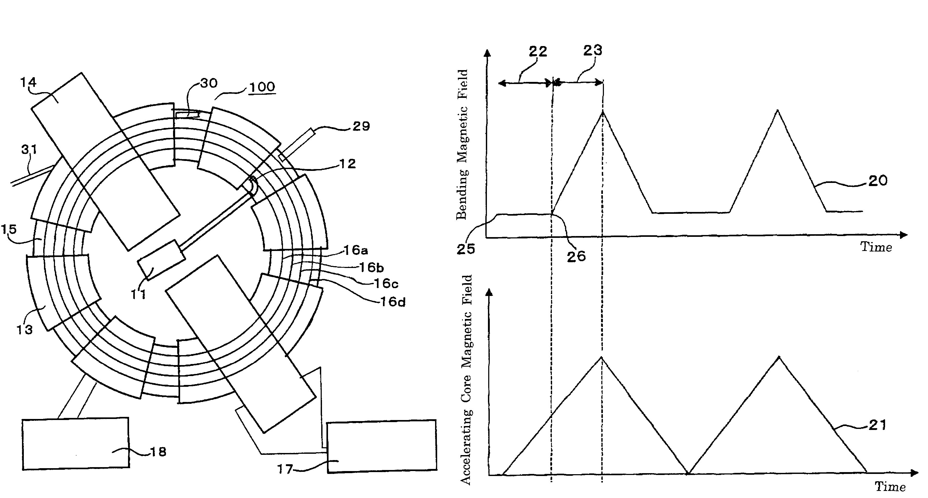
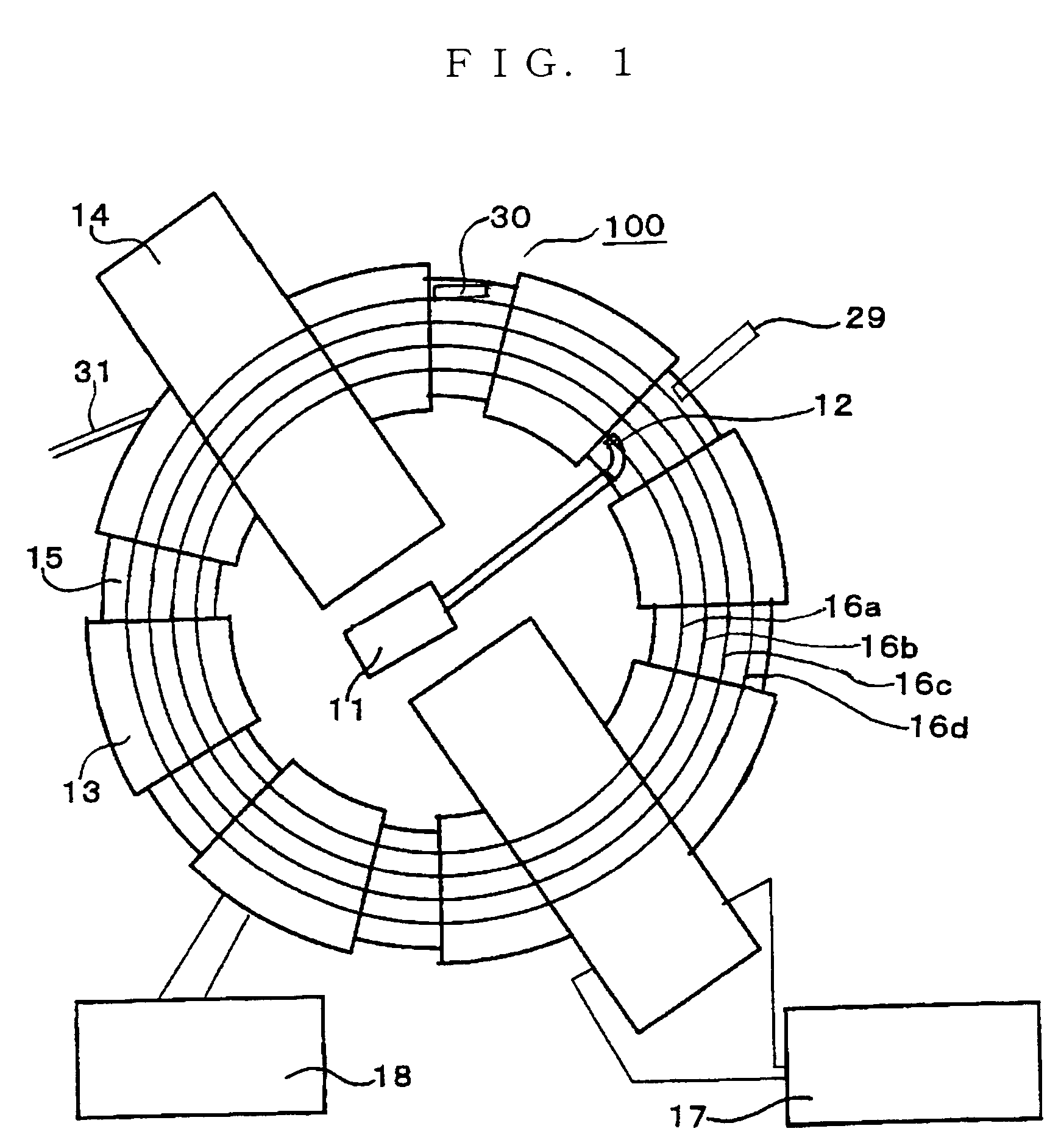
[0023]FIG. 1 is a plan view showing a charged particle accelerator 100.

[0024]In FIG. 1, a charged particle beam (hereinafter referred to as beam) generated by a charged particle generating apparatus 11 is injected from a septum electrode 12 into a vacuum duct 15. The beam is bent by a bending magnet 13 and circulated along a substantially circular orbit. The acceleration of the beam is carried out by induced electric field generated through magnetic induction by applying alternating excitation from an acceleration core power source 17 to an acceleration core 14. The beam circulates in the vacuum duct 15 so that the beam is prevented from impinging against air and thus being lost. Representative equilibrium orbits thereof are schematically represented by 16a, 16b, 16c, 16d.

[0025]The bending magnet 13 is excited by a power source 18 for the bending magnet. The acceleration core ...

embodiment 2

[0036]An embodiment 2 of the present invention will be described with reference to FIG. 3.

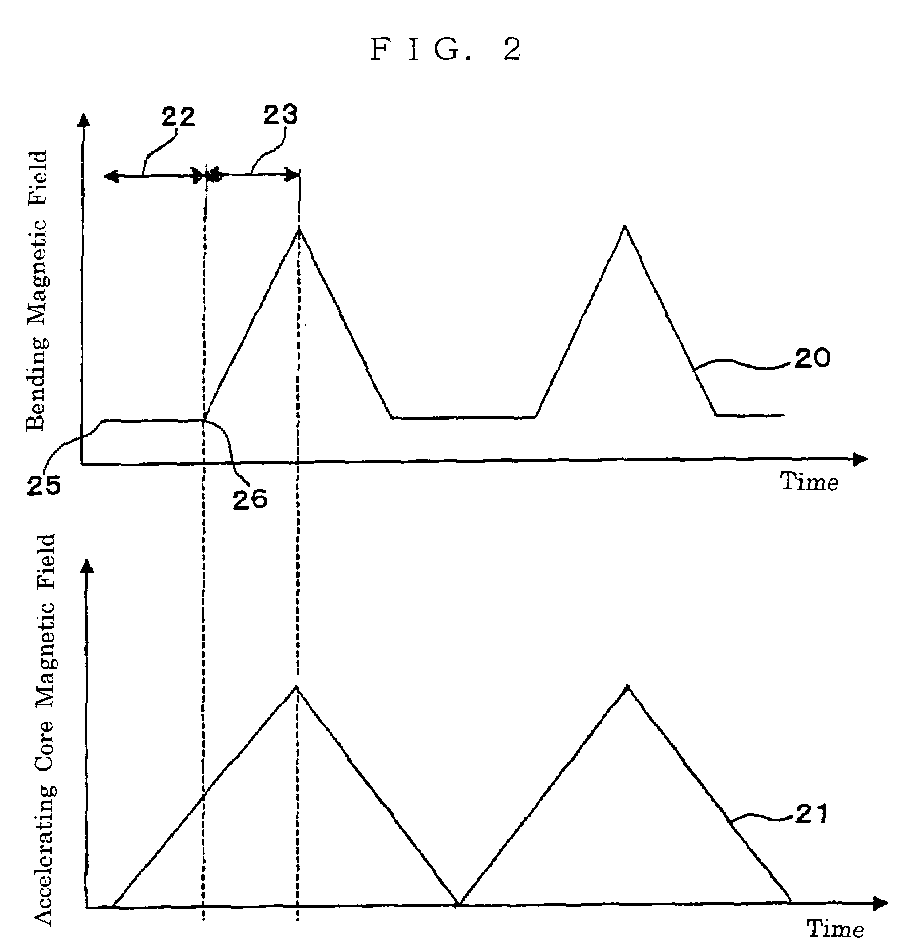
[0037]FIG. 3 is time structures of the bending magnetic field 20 and the acceleration core magnetic field 21 according to the embodiment 2 as in the case of the embodiment 1.

[0038]As shown in FIG. 3, in the embodiment 2 of the present invention, the acceleration core magnetic field 21 is applied such that it is set to a minus value at the start time 25 of the first acceleration period 22, that is, at the time point of the beam injection start time 25, and then increased in a plus direction with time lapse until the end time of the second acceleration period 23.

[0039]That is, the acceleration core magnetic field 21 exhibits such a time structure that positive and negative magnetic field occurs. When a beam is accelerated on the basis of the time structure of the acceleration core magnetic field 21 as described above, the space charge effect can be suppressed, and high power beam can be attained ...

embodiment 3

[0040]An embodiment 3 of the present invention will be described with reference to FIGS. 3 and 4.

[0041]FIG. 4 is a diagram showing the time structures of the bending magnetic field 20 and the acceleration core magnetic field 21 in the embodiment 3.

[0042]In the embodiment 3, the time structure of the bending magnetic field 20 is increased with time lapse from the first acceleration period start time 25 until the first acceleration period end time 26. That is, the bending magnetic field 20 is varied during the first acceleration period 22. At this time, the beam energy of the charged particle generating apparatus 11 is required to be also varied. When the beam is accelerated on the basis of the time structure of the bending magnetic field 20 as described above, the space charge effect can be suppressed, and high power beam can be accelerated by a compact apparatus as in the case of the above embodiments.


PUM


Abstract

The present invention provides a charged particle accelerator comprising a charged particle generating apparatus, a bending magnet, accelerating means and a vacuum duct, wherein first and second acceleration periods (22), (23) are provided, accelerating electric field of the accelerating means is applied from the start time (25) of the first acceleration period (22) until the end time of the second acceleration period (23), and bending magnetic field is applied at a fixed value during the first accelerating period while, during the second acceleration period, it is applied so as to increase until the end time of the second acceleration period. Accordingly, there is provided a compact and high power charged particle accelerator which can perform large-current acceleration.

Description

TECHNICAL FIELD[0001]This application is a 371 of PCT / JP04 / 0140 Feb. 12, 2004.[0002]The present invention relates to a circular particle accelerator for accelerating charged particles, and particularly to a compact charged particle accelerator for enabling acceleration of a large-current beam.BACKGROUND ART[0003]As a conventional charged particle accelerator is known an FFAG (Fixed Field Alternating Gradient) accelerator in which magnetic field generated by a bending magnet is fixed and an equilibrium orbit is expanded to the outside of a round orbit while accelerating charged particles. (See non-patent document 1, for example).[0004]Furthermore, a betatron is known as an accelerator in which an equilibrium orbit is not varied and acceleration is carried out along a fixed orbit. (See non-patent document 2, for example).[0005][Non-patent document 1][0006]“Development of a FFAG proton synchrotron” Proceedings of EPAC 2000, Vienna Austria 2000. pp 581-583, FIG. 1.[0007][Non-patent Docu...

Claims


Application Information

Patent Timeline
Patent Type & Authority Patents(United States)
IPC IPC(8): H05H7/00H05H11/00
CPCH05H11/00
Inventor TANAKA, HIROFUMI
Owner MITSUBISHI ELECTRIC CORP
Why Eureka
Try Eureka