Magnetic field sensor and method for operating the magnetic field sensor

a magnetic field sensor and magnetic field technology, applied in the field of magnetic field sensors, can solve the problems of not being suitable for battery operation applications, relative high current is needed for magnetic saturation, etc., and achieve the effect of reducing the volume of the core, shortening the current pulse for magnetization, and reducing the total required energy

Inactive Publication Date: 2007-08-21
MELEXIS TECH NV
View PDF18 Cites 76 Cited by
  • Summary
  • Abstract
  • Description
  • Claims
  • Application Information

AI Technical Summary

Benefits of technology

[0012]A further advantage of reducing the volume of the core exists in that the build up of the premagnetization by means of a magnetic field produced by the coil is itself less inhibited by eddy currents produced in the core. In this way, the current pulse for magnetization can be shorter and the total required energy reduced. A sensor optimised in this way is also suitable for applications with little admissible energy consumption such as a watch for example.

Problems solved by technology

The disadvantage with such a sensor is that a relatively high current is necessary for the magnetic saturation of the ferromagnetic core.
Such a magnetic field sensor is therefore not suitable for applications with battery operation.
Investigations have revealed that a significant problem exists in that the ferromagnetic core serving as magnetic field concentrator can be magnetized or the magnetization can be reversed to such an extent by an external, for example temporarily occurring magnetic interference field, that the ferromagnetic core becomes a magnetic dipole that produces a signal in the read-out coils.

Method used


Image

  • Magnetic field sensor and method for operating the magnetic field sensor
  • Magnetic field sensor and method for operating the magnetic field sensor
  • Magnetic field sensor and method for operating the magnetic field sensor

Examples


embodiment 1

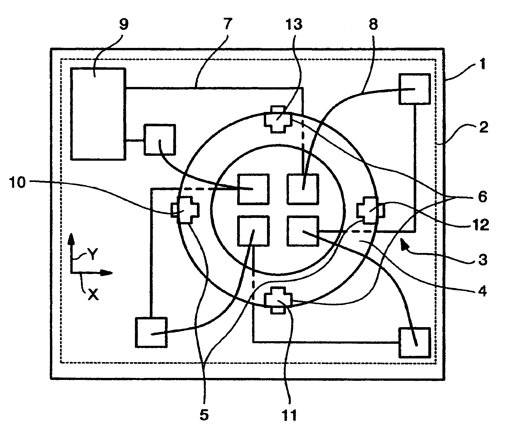
[0021]FIG. 1 shows a plan view of a magnetic field sensor formed as a semiconductor chip 1 for the measurement of two components of an external magnetic field. A Cartesian system of x, y, z co-ordinates serves as reference system the origin of which in the figure, for reasons of illustrative clarity, is arranged outside the magnetic field sensor, whereby the z direction runs vertically to the plane of projection. The magnetic field sensor comprises an electronic circuit 2, an excitation coil 3 to which current can be applied with, for example, four turns, a ring-shaped ferromagnetic core 4 and two read-out sensors 5, 6. The ferromagnetic core 4 extends in a plane and therefore defines the position of the xy plane. The read-out sensor 5 serves the acquisition of the x component of the magnetic field, the read-out sensor 6 serves the acquisition of the y component of the magnetic field. The read-out sensors 5, 6 consist preferably of two locally separated but electrically connected se...

embodiment 2

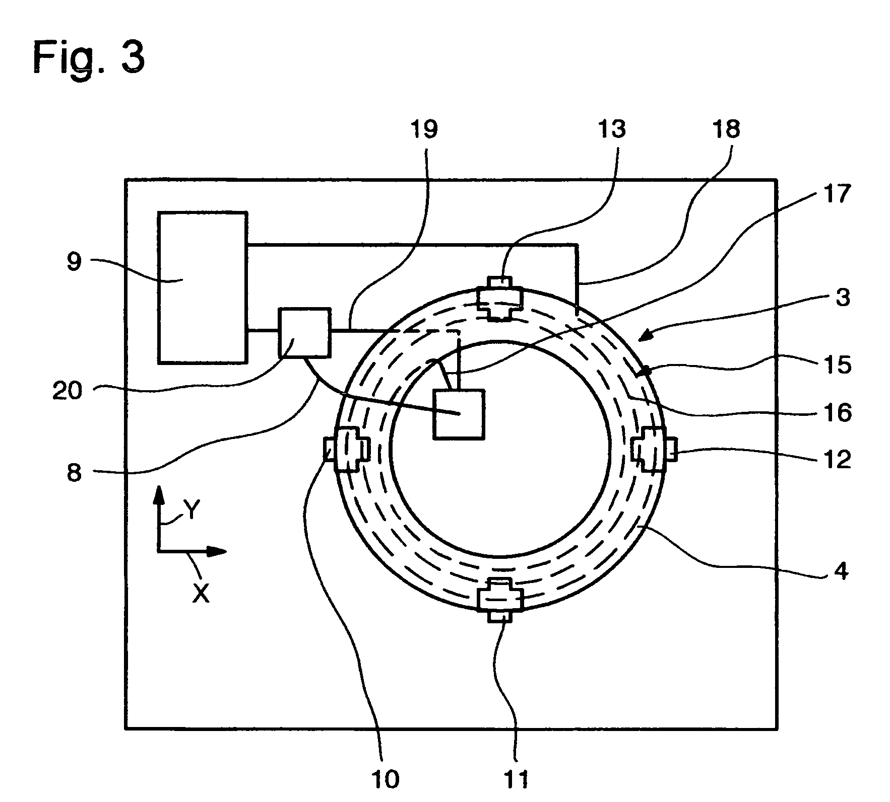
[0033]FIG. 3 shows a plan view of a further magnetic field sensor with a ring-shaped ferromagnetic core 4 with which the excitation coil 3 is formed as a flat coil 15 with a spiral conductor path 16 that is arranged underneath the ferromagnetic core 4. The conductor path 16 runs spirally but nevertheless almost concentrically to the ferromagnetic core 4.

[0034]A first end 17 of the conductor path 16 is naturally located within, a second end 18 of the conductor path16 outside the ring-shaped ferromagnetic core 4. A conductor path 19 arranged in a second metallisation layer connects the first end 17 with a connection 20 arranged outside the ring-shaped ferromagnetic core 4. (The bond wire 8 also illustrated is not present for the second embodiment but is important for the third embodiment.) The conductor path 19 is therefore located on the same side of the ferromagnetic core 4 as the flat coil 15. Although the conductor path 16 of the flat coil 15 runs spirally, parts of the conductor ...

embodiment 3

[0035]This example largely corresponds to the second embodiment but instead of the conductor path 19, the bond wire 8 is present that connects the first end 17 of the flat coil 15 with a connection 20 arranged outside the ring-shaped ferromagnetic core 4. Because the flat coil 15 and the bond wire 8 cross the ferromagnetic core 4 on different sides, namely the flat coil 15 underneath and the bond wire 8 above, the result is a supplementary coil with one single winding that encloses the ring of the ferromagnetic core 4 and works as an excitation coil in accordance with the first embodiment. In contrast to the second embodiment, the current flowing through the bond wire 8 does not compensate the current flowing in radial direction through the flat coil 15. The combination of flat coil 15 and bond wire 8 represents an excitation coil 3 with which the ferromagnetic core 4 can be brought into a state of predetermined magnetization in a very efficient way in which the magnetization of the...


PUM


Abstract

A magnetic field sensor for the measurement of at least one component of a magnetic field comprises a ferromagnetic core that serves as a magnetic field concentrator, an excitation coil and a read-out sensor. The read-out sensor preferably comprises two sensors arranged in the vicinity of the outer edge of the ferromagnetic core and measures the at least one component of the magnetic field. The ferromagnetic core is ring-shaped or disc-shaped. On operation of the magnetic field sensor, a current is temporarily applied to the excitation coil in order to bring the ferromagnetic core into a state of predetermined magnetization in which the magnetization of the ferromagnetic core produces no signal in the read-out sensor.

Description

CROSS REFERENCE TO RELATED APPLICATIONS[0001]The present application is related to and claims priority of the PCT application number PCT / EP03 / 50342 of Sentron AG entitled Magnetic field sensor and method for operating the magnetic field sensor, filed on Jul. 29, 2003, the disclosure of which is herein incorporated by reference, which in turn claims priority of the PCT applications number PCT / CH02 / 00428 filed Aug. 1, 2002 and PCT / CH02 / 00507 filed Sep. 16, 2002.FIELD OF THE INVENTION[0002]The invention concerns a magnetic field sensor and a method for operating a magnetic field sensor of the type named in the preamble of claim 1.[0003]Such magnetic field sensors are suitable for the measurement of magnetic fields the strength of which amounts only to some nT to mT, for example as a compass for measuring the direction of the earth's magnetic field.BACKGROUND OF THE INVENTION[0004]A magnetic field sensor for measuring magnetic fields is known from EP 1 182 461. The magnetic field sensor...

Claims


Application Information

Patent Timeline
Patent Type & Authority Patents(United States)
IPC IPC(8): G01R33/025G01R35/00G01R33/07G01D5/14G01R33/04G01R33/06
CPCG01R33/04G01R33/06G01D5/14
Inventor POPOVIC, RADIVOJESCHOTT, CHRISTIAN
Owner MELEXIS TECH NV
Why Eureka
Try Eureka