Method and apparatus for encoding and decoding digital communications data

a digital communication and data encoding technology, applied in the direction of cross-talk reduction, pulse technique, line-transmission details, etc., can solve the problems of enhancing the difficulty in recovering the original signal at the receiver, and reducing the recovery or detection of the original signal. , to achieve the effect of reducing reducing the transition between extreme signaling levels, and reducing the crosstalk and intersymbol interferen

Active Publication Date: 2007-08-21
SYNOPSYS INC
View PDF5 Cites 58 Cited by
  • Summary
  • Abstract
  • Description
  • Claims
  • Application Information

AI Technical Summary

Benefits of technology

[0012]In one aspect, the present invention is a system and technique that provides for the systematic development or implementation of codes that increase the robustness of systems employing, for example, PAM-n transmission techniques. The system and technique of this aspect of the invention eliminate, minimize, reduce or limit transitions between extreme signaling levels. As a result, the slew rate employed and / or required by the transmitter reduces crosstalk and intersymbol interference, and provides for wider “eye” openings at the receiver.
[0013]In addition, symbols that arise as a result of min-max-min or max-min-max signaling levels, which may be eliminated, minimized, reduced or limited in accordance with the present invention, tend to suffer significant impairment or degradation when transmitted through a band-limited communications channel. Thus, eliminating, reducing or restricting such symbol transitions may improve the “eye” opening from the perspective of the receiver.

Problems solved by technology

The reduction in voltage margin creates, among other things, the recovery or detection of the original signal more difficult and therefore recovery of the original symbol(s) more difficult.
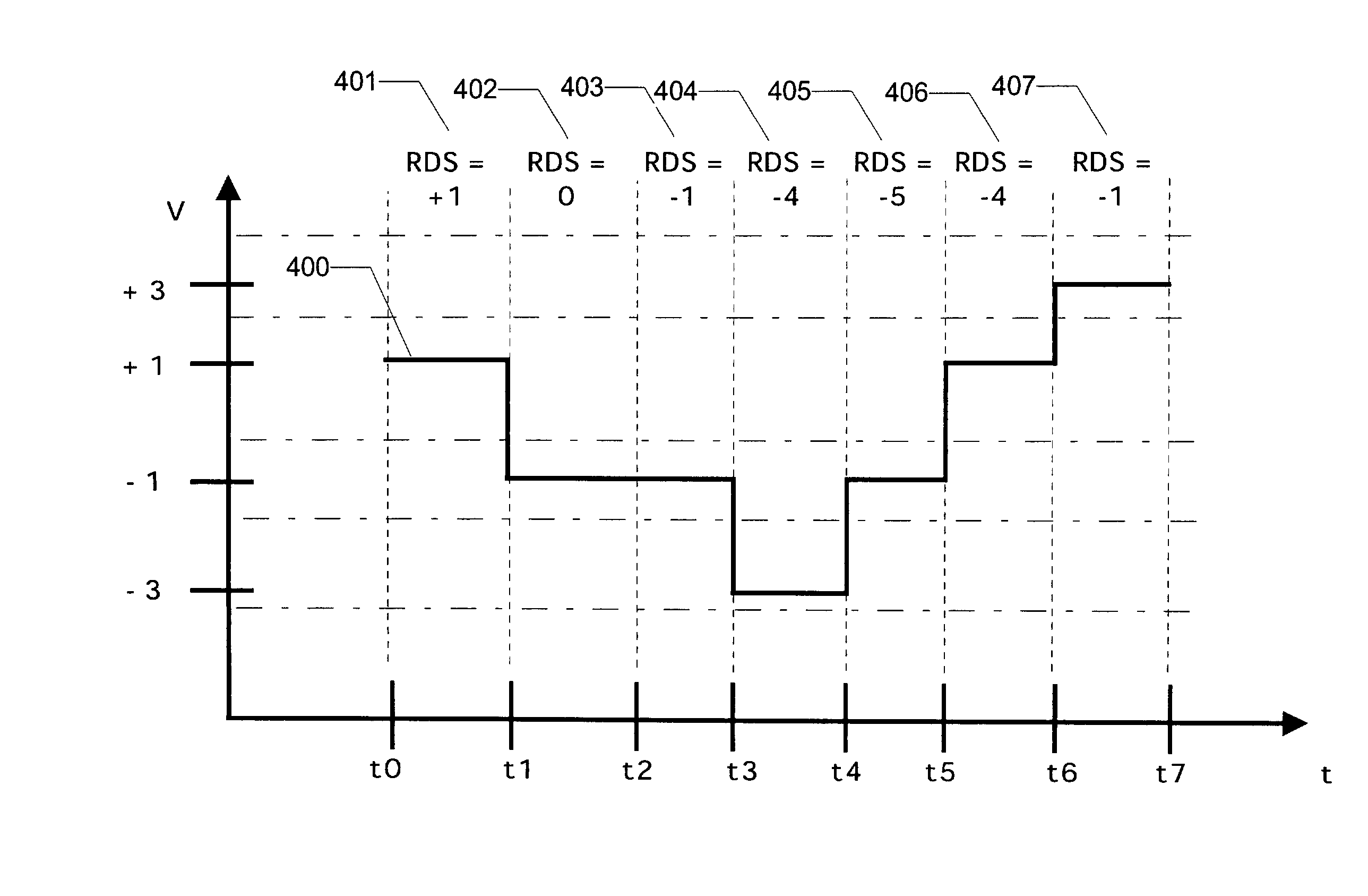
That is, a transition from the highest to lowest allowable signal levels, for example, transition from a signal level of +3 to a signal level of −3, may enhance the difficulty in recovery of the signals at the receiver because such transitions tend to narrow the “eye” openings from the perspective of the receiver.

Method used


Image

  • Method and apparatus for encoding and decoding digital communications data
  • Method and apparatus for encoding and decoding digital communications data
  • Method and apparatus for encoding and decoding digital communications data

Examples


Embodiment Construction

[0022]In the following detailed description of exemplary embodiments of the invention, reference is made to the accompanied drawings, which form a part hereof, and which is shown by way of illustration, specific exemplary embodiments of which the invention may be practiced. These embodiments are described in sufficient detail to enable those skilled in the art to practice the invention, and it is to be understood that other embodiments may be utilized, and other changes may be made, without departing from the scope of the present invention. The following description is, therefore, not to be taken in a limiting sense, and the scope of the present invention is defined by the appended claims.

[0023]Throughout the specification and claims, the following terms take the meanings explicitly associated herein, unless the context clearly dictates otherwise. The term “connected” means a direct connection between the items connected, without any intermediate devices. The term “coupled” means ei...


PUM


Abstract

In one aspect, the present invention is a system and technique that provides for the systematic development or implementation of codes that increase the robustness of systems employing, for example, PAM-n transmission techniques. The system and technique of this aspect of the invention eliminate, minimize, reduce or limit transitions between extreme signaling levels. As a result, the slew rate employed and / or required by the transmitter may reduce crosstalk and intersymbol interference, and provide for wider “eye” openings from the perspective of the receiver.

Description

CROSS-REFERENCE TO RELATED APPLICATIONS[0001]This application claims priority to U.S. Provisional Patent Application Ser. No. 60 / 313,476, entitled “Method and Apparatus for Encoding and Decoding Digital Communications Data”, filed Aug. 20, 2001 and U.S. Provisional Application Ser. No. 60 / 313,214, entitled “Transceiver Apparatus and Method”, filed Aug. 17, 2001. The contents of these provisional applications are incorporated, in their entirety, by reference herein.[0002]This application is related to U.S. Provisional Patent Application Ser. No. 60 / 313,454, entitled “Transceiver System for High Speed Digital Signaling”, filed Aug. 20, 2001; U.S. Provisional Patent Application Ser. No. 60 / 313,455, entitled “Automatic Slicer Level Adaption”, filed Aug. 20, 2001; U.S. Provisional Patent Application Ser. No. 60 / 313,456, entitled “Variable Rate Sub-Channel Using Block Code RDS”, filed Aug. 20, 2001; U.S. Provisional Patent Application Ser. No. 60 / 313,478, entitled “Variable Delay FIR Equa...

Claims


Application Information

Patent Timeline
Patent Type & Authority Patents(United States)
IPC IPC(8): H04L25/34H04L25/49H03K7/02H04B3/32H04B3/46
CPCH04B3/32H04B3/487H04L25/4919
Inventor STONICK, JOHN T.GORECKI, JAMESCHECK, JR., WILLIAM S.SEARLES, SHAWN
Owner SYNOPSYS INC
Why Eureka
Try Eureka