
Displays

a technology of illumination technology and displays, applied in the field of displays and illumination technology, can solve the problem of method consuming electrical power, and achieve the effect of not using

Inactive Publication Date: 2007-08-21
THE COURT OF EDINBURGH NAPIER UNIV
View PDF11 Cites 18 Cited by
  • Summary
  • Abstract
  • Description
  • Claims
  • Application Information

AI Technical Summary

Benefits of technology

[0028]In an alternative preferred embodiment of this dielectric stack, thin films of two different polymers, with the two different refractive indices, can be applied to the polymer surface sequentially and vacuum pressed and / or thermally treated for each layer. This method has the advantage that it allows larger areas to be covered by the dielectric stack mirror.

Problems solved by technology

Previous application involving such materials had the disadvantage that the sign or display element required illumination through the means of applying an external electrical power supply with this electrical power requiring conversion into light power and consequently this method consumes electrical power.

Method used


Image

  • Displays
  • Displays
  • Displays

Examples


Embodiment Construction

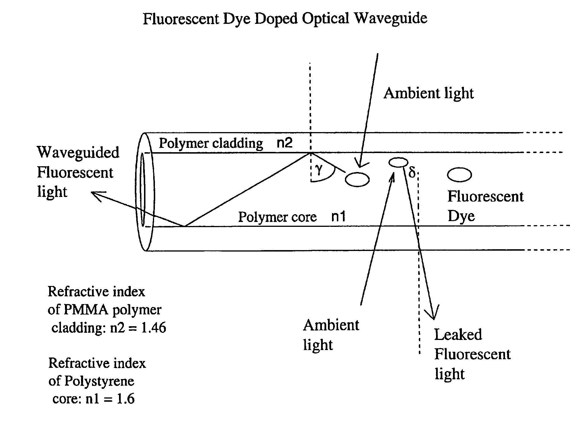
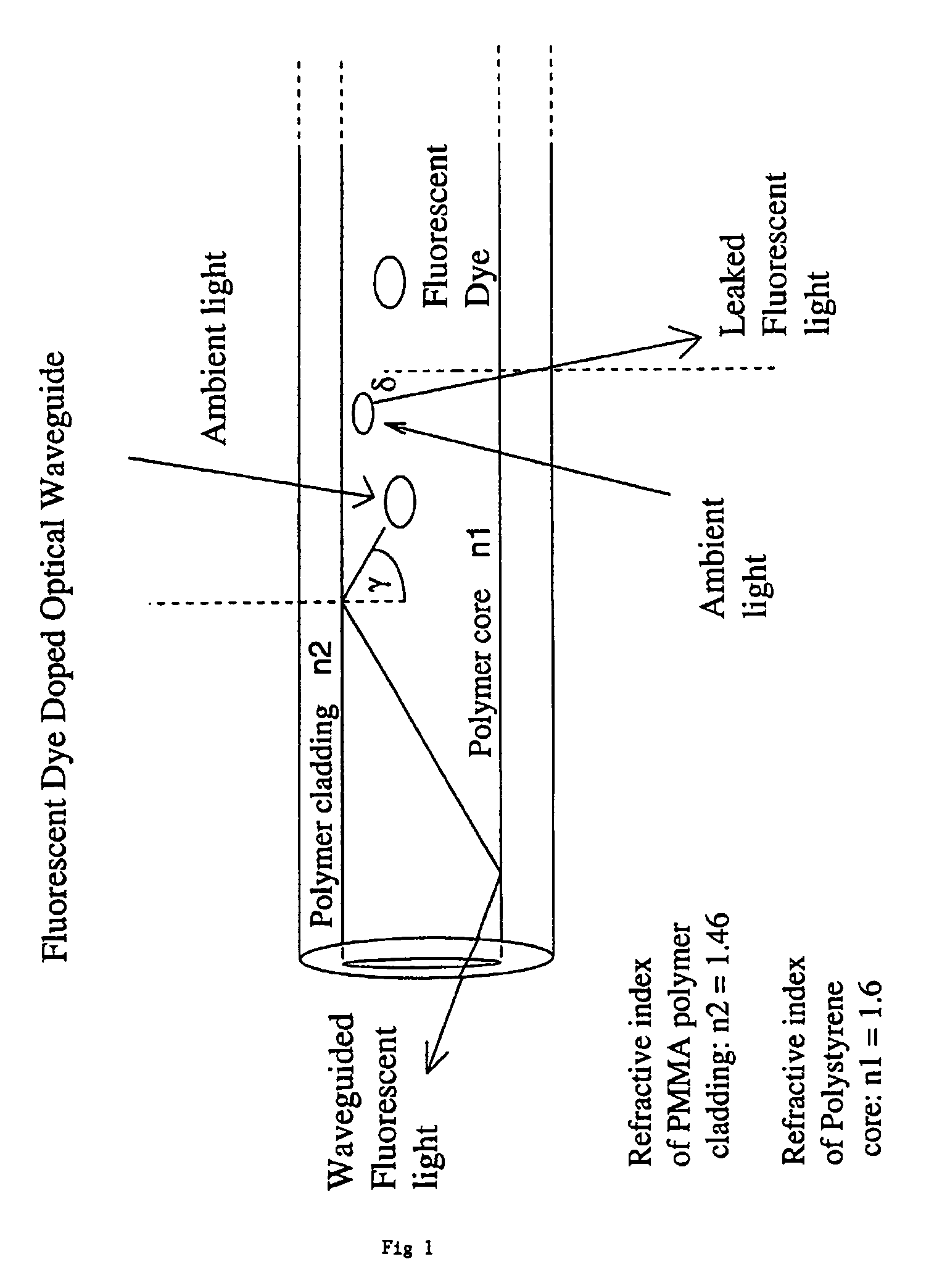
[0109]As a first example of the invention FIG. 1 describes the structure of the light emitting polymer in reflective mode. The transparent polymer is chemically doped or blended with a fluorescent dye. The fluorescent dye should have a high quantum efficiency for converting natural light or indoor light into some visible colour. The bottom surface and edges of the polymer are covered with a highly reflective additional layer which acts as a mirror and ensures that all light entering through the top surface is fully reflected back into the polymer.

[0110]The top surface of the polymer is covered with a dielectric stack mirror which comprises two dielectric films with alternating high and low refractive indices. This dielectric stack serves as an interference filter allowing 100% transmission of light from the air to the polymer for the wavelengths used for excitation of the fluorescent dyes doped within the polymer. The dielectric stack however has a near 100% reflection for light wav...


PUM

PropertyMeasurementUnit
Fractionaaaaaaaaaa
Radiusaaaaaaaaaa
Radiusaaaaaaaaaa

Abstract

The present invention describes a fluorescent dye doped polymer based optical wave-guide structure. The described polymers can be used to fabricate a range of display elements and illumination systems which work without the use of external electrical power. This is due to the process of the fluorescent dyes absorbing ambient light and then subsequently emitting light which is conducted by the polymer host material to a point where it is emitted. The emitted light can be of a range of colours depending upon the type of dye that polymers are doped with. There is a constant contrast between the light power flux emitted for the wave-guide structure and the light power flux of the ambient light. There is also provided a method in which a dielectric stack mirror layer fabricated on the surface of the polymer which can be used to improve the efficiency and the contrast of those optical elements.

Description

CROSS-REFERENCE TO RELATED APPLICATION[0001]This application is a continuation of application Ser. No. 09 / 744,709 filed Jan. 29, 2001 now abandoned.FIELD OF THE INVENTION [0002]This invention relates to display and illumination technology.[0003]The present invention describes a method in which polymers doped with fluorescent dyes can be used to fabricate display elements and illumination systems for use in applications such as road signs, advertisement displays, toys etc whereby the use of external electrical power is not required. The fluorescent dyes with which these polymers are doped, absorb ambient light, before emitting light which is conducted by the polymer host material to the end of the fibre where the emitted light is of a much greater light power density than the light power density of the ambient light.SUMMARY OF THE INVENTION[0004]In this field it is already known that flat panel display elements composed out of plastic polymers can be used as display articles and that...

Claims


Application Information

Patent Timeline
IPC IPC(8): G02B6/00F21V8/00G02B1/04
CPCG02B1/046G02B6/0003G02F1/011G02F1/0126
Inventor HAJTO, JANOSHINDLE, COLINGRAHAM, ANDREW
Owner THE COURT OF EDINBURGH NAPIER UNIV
Learn More