Distributed control system

a control system and distribution system technology, applied in the field of distribution control system, can solve the problems of vehicle control system, inability to ensure the synchronization of sensor information,

Inactive Publication Date: 2007-08-21
DENSO CORP
View PDF9 Cites 33 Cited by
  • Summary
  • Abstract
  • Description
  • Claims
  • Application Information

AI Technical Summary

Problems solved by technology

In such a vehicle control system, if an ECU whose wiring configuration has been changed is designed to control a target device using pieces of sensor information whose measured timings are synchronized with each other (kept in phase with each other), the following significant disadvantage may appear in the vehicle control system.
This may not ensure the synchronism between the pieces of sensor information.
In this regard, the vehicle control system disclosed in the U.S. Patent Publication No. 6,711,472 B2 cannot solve the disadvantage set forth above because it aims at synchronization between an ECU and sensors connected thereto, and therefore does not focus on synchronism of pieces of sensor information to be obtained from sensors connected to different ECUs, respectively.

Method used


Image

  • Distributed control system
  • Distributed control system
  • Distributed control system

Examples


first embodiment

[0035]In a first embodiment of the present invention, a distributed control system according to the present invention is applied to a vehicle control system that has been installed in a vehicle.

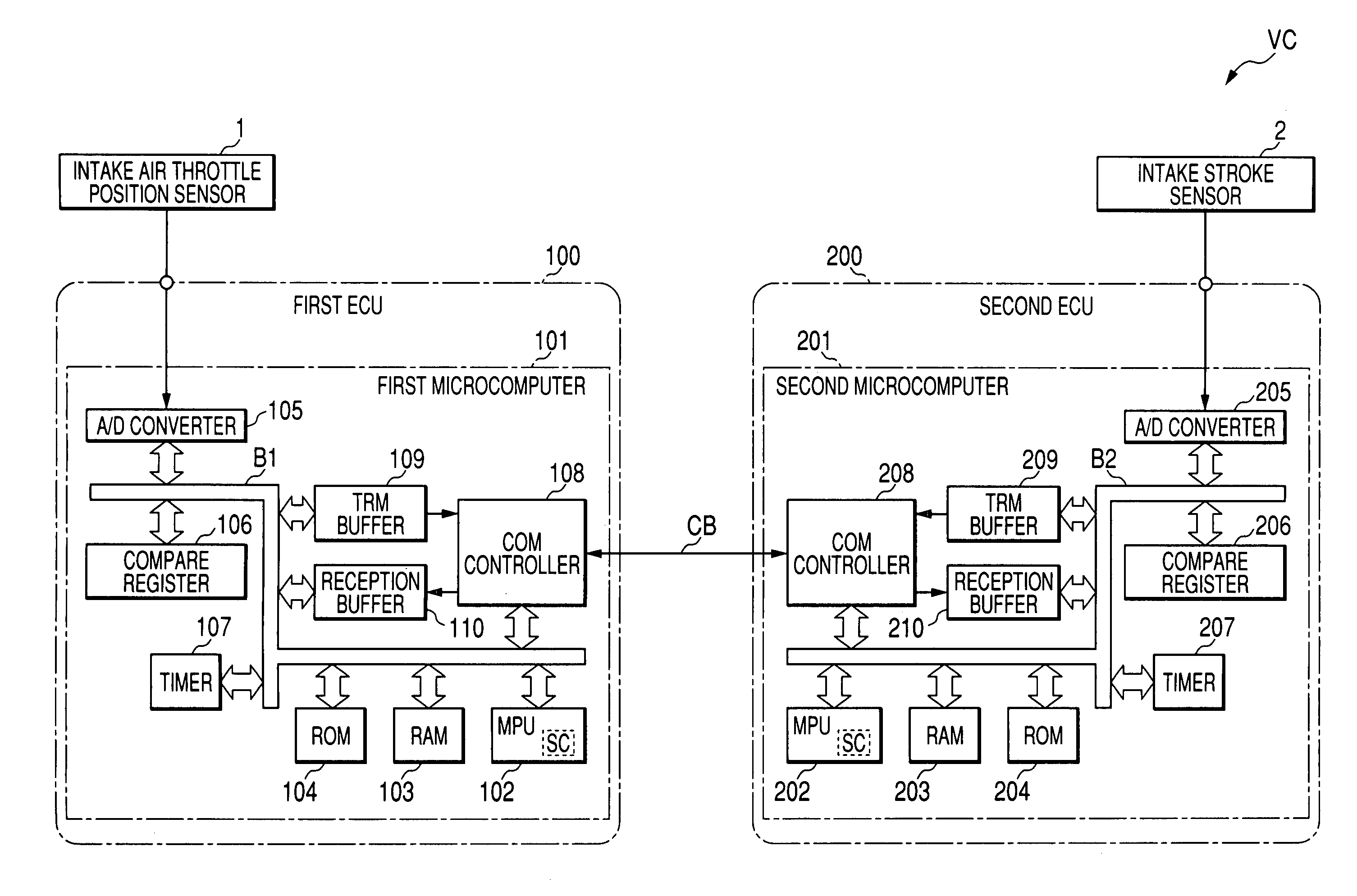
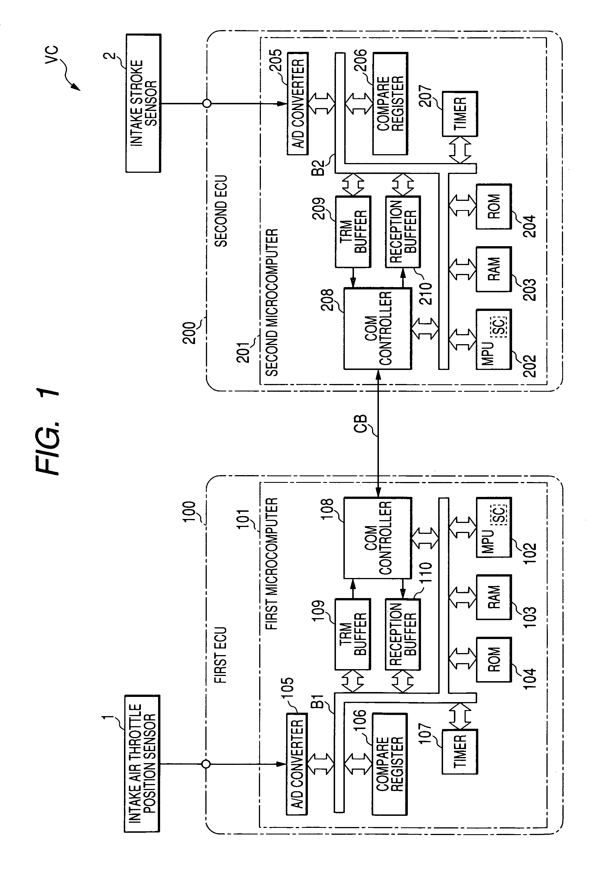
[0036]As illustrated in FIG. 1, the vehicle control system VC according to the first embodiment includes a first ECU (electronic control unit) 100 for execution of an allocated control of the vehicle, such as engine control, and a second ECU 200 for execution of allocated control of the vehicle, such as actuator-drive control. The first ECU 100 and the second ECU 200 are communicably linked to each other via a CAN bus CB.

[0037]The first ECU 100 is communicably connected to an intake throttle-position sensor 1 installed in the vehicle. The intake throttle-position sensor 1 is preferably configured to continuously monitor information representing throttle position of an intake throttle of the engine and to send, to the first ECU 100, the monitored throttle position information as analog sensor ...

second embodiment

[0187]In a second embodiment of the present invention, a distributed control system according to the present invention is applied to a vehicle control system that has been installed in a vehicle. Note that like reference characters are assigned to like parts in the vehicle control systems according to the first and second embodiments so that descriptions of the parts will be omitted.

[0188]As illustrated in FIG. 15, the vehicle control system VC 1 according to the second embodiment includes a time management ECU 300 in addition to the first ECU 100 and the second ECU 200. The first ECU 100, the second ECU 200, and the time management ECU 300 are communicably linked to each other via the CAN bus CB.

[0189]The time management ECU 300 has substantially the same configuration as that of the first ECU 100 or the second ECU 200. Specifically, the time management ECU 300 includes a microcomputer, and the microcomputer is composed of an MPU, a RAM, a ROM, a transmission buffer, a reception bu...


PUM


Abstract

In a distributed control system, a first electronic control unit sends trigger information to a second electronic control unit. The trigger information includes a timing that triggers the second electronic unit to obtain second sensor information from a second sensor. The second electronic control unit is designed to receive the trigger information, and obtain, at the timing of the trigger information, the second sensor information from the second sensor. The second electronic unit is configured to send, to the first electronic control unit, the obtained second sensor information.

Description

CROSS REFERENCE TO RELATED APPLICATIONS[0001]This application is based on Japanese Patent Application 2005-141726 filed on May 13, 2005. This application claims the benefit of priority from the Japanese Patent Application, so that the descriptions of which are all incorporated herein by reference.FIELD OF THE INVENTION[0002]The present invention relates to a distributed control system including a plurality of electronic control units communicably linked to each other, which are capable of executing distributed control tasks using pieces of sensor information obtained from a various types of sensors.BACKGROUND OF THE INVENTION[0003]With in-vehicle devices, such as a transmission, an air conditioner, and so on, being highly advanced, a large number of electronic control units constituting a conventional vehicle control system have been installed in a vehicle. These electronic control units, referred to simply as ECUs, are distributedly located to individually control corresponding pre...

Claims


Application Information

Patent Timeline
Patent Type & Authority Patents(United States)
IPC IPC(8): G06F1/04G06F15/16G06F17/00G06F19/00G06F3/00G06F7/00H04L7/00F02D41/26F02D45/00
CPCG05B19/4148G05B2219/33278G05B2219/34413H04J3/0638H04L7/10
Inventor ICHIKAWA, TAKAHIRONAKANO, TAKASHIHAYASHI, SHINICHI
Owner DENSO CORP
Why Eureka
Try Eureka