
Sealable ceiling assembly

a ceiling assembly and sealable technology, applied in the field of clean room systems, can solve the problems of requiring considerable installation time, requiring comparatively complex methods, and requiring considerable process time, and achieve the effects of convenient installation, considerable bending support, and high section modulus

Active Publication Date: 2007-08-28
AIRTEX MFG LLLP
View PDF26 Cites 36 Cited by
  • Summary
  • Abstract
  • Description
  • Claims
  • Application Information

AI Technical Summary

Benefits of technology

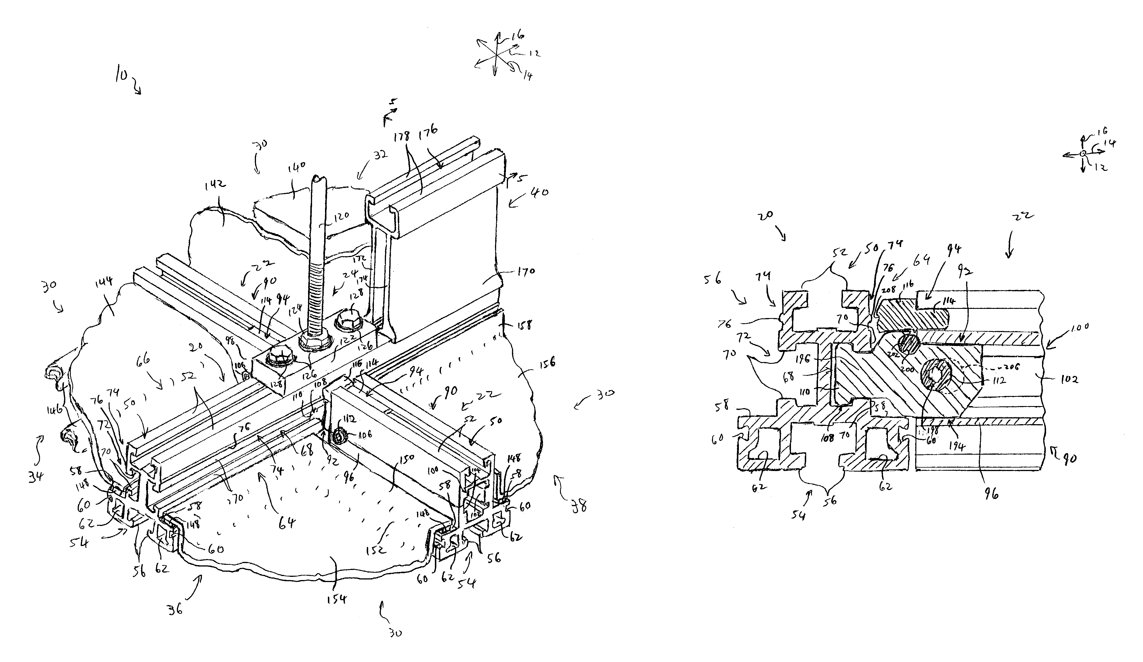
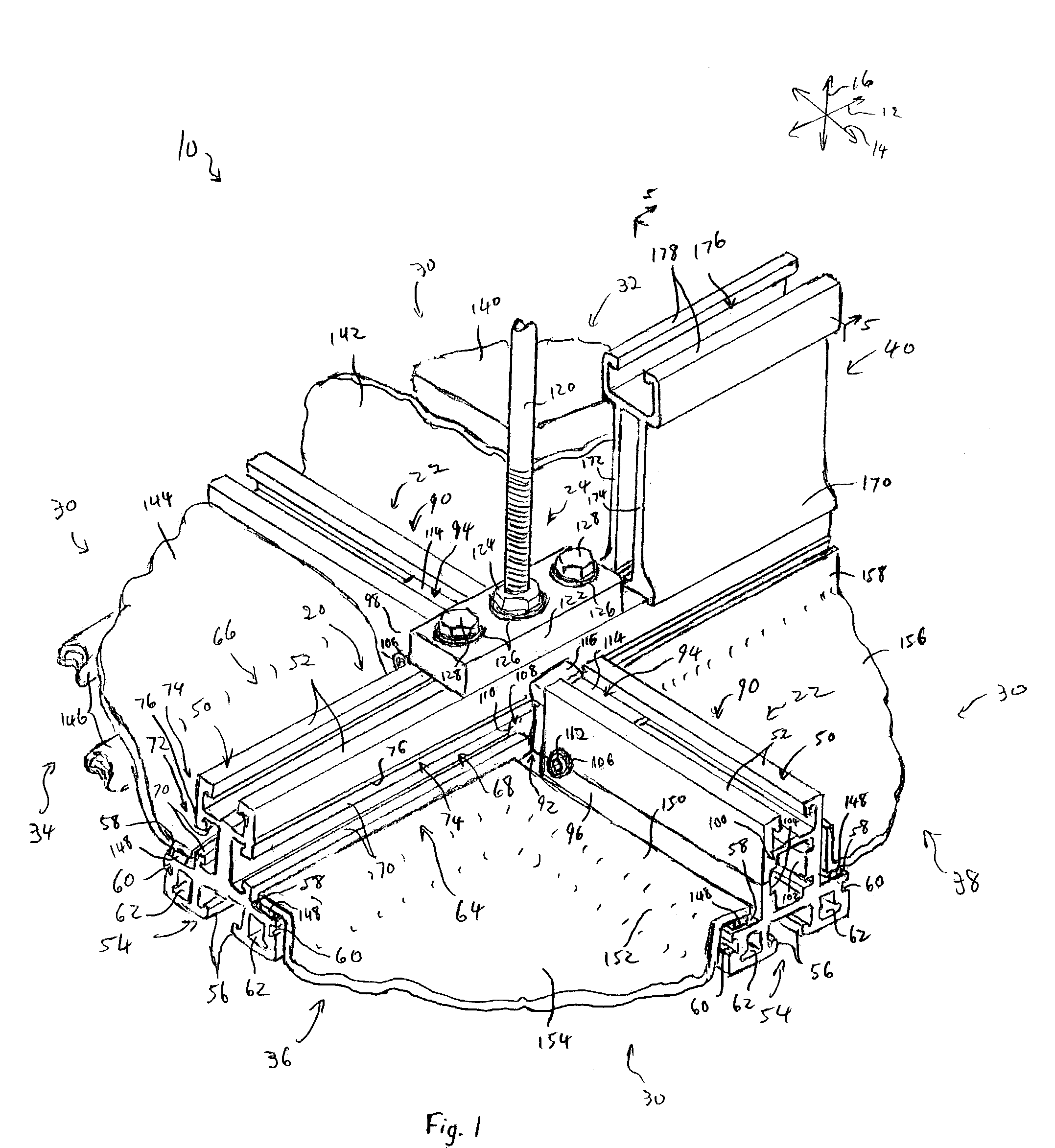
[0013]To achieve the foregoing objective, and in accordance with the invention as embodied and broadly described herein in one embodiment, a sealable ceiling assembly is provided. The sealable ceiling assembly has at least one main beam perpendicularly coupled to a plurality of cross beam assemblies. The main beam is suspended from a support ceiling via hanger rod assemblies, which may be positioned at intersections of the main beam with the cross beam assemblies. A plurality of structures such as filter units, light fixtures, flush blank panels, and recessed blank panels, are disposed in spaces defined by the main beam and the cross beam assemblies. The structures are substantially sealed to the main beam and the cross beam assemblies so that air is only able to enter the clean room envelope through the filter units. One or more stiffeners are attached to the beams to enhance bending resistance of the beams.
[0014]The main beam has a top nut slot with inwardly extending lips designed to facilitate retention of the hanger rod assemblies. Furthermore, the main beam has a bottom nut slot with inwardly extending lips that facilitate hanging of various structural items, such as lighting, sprinklers, or production equipment such as an automated materials handling system (AMHS). The main beam has shelves on either side on which the aforementioned structures may rest. The main beam also has lateral grooves on either side to facilitate attachment of the aforementioned structures or the like.
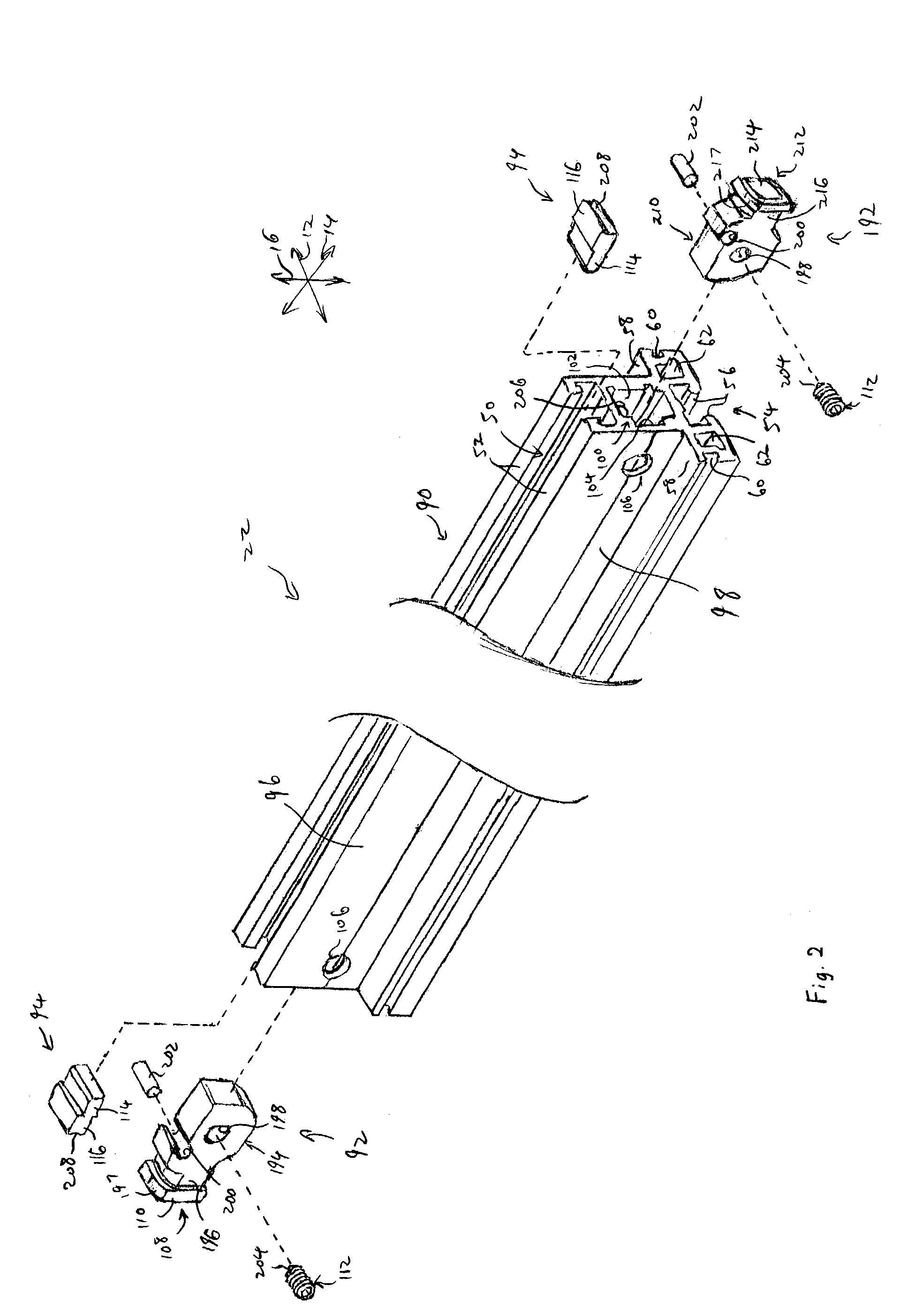
[0023]Once assembled, the coupling members are inserted into the bore of the cross beam at the first and second ends. Each set screw moves into general alignment with a generally conical countersink formed in the plateau within the bore. The set screws are actuated a small distance into the generally conical countersinks so that the coupling members cannot be withdrawn from the bore without loosening the set screws. The resilient members press against the cross beam to urge the coupling members to protrude as far as possible from the bore, thereby facilitating installation
[0030]The attachment portion of the stiffener has lateral extensions that extend along the width of the top nut slot to provide a stable fit between the attachment portion and the beam. The attachment portion also has a trough with a plurality of holes, each of which permits passage of a threaded end of a bolt into the top nut slot. The bolts are anchored in T-nuts or other devices disposed and retained within the top nut slot of the beam. Each bolt has a head seated in the top nut slot of the stiffener such that the bolts can be tightened to press the attachment portion against the beam.
[0031]The support webs extend vertically from the beam, thereby providing a relatively high section modulus for the beam / stiffener combination. Consequently, the stiffener lends considerable bending support to the beam, and is easily installed without requiring disassembly of any part of the sealable ceiling assembly.
[0032]Through the use of the sealable ceiling assembly and related methods presented herein, a sealed ceiling may be rapidly installed or modified with a minimum of contaminant production. Furthermore, reinforcement may be easily and cost-effectively added to facilitate use with hanging clean room equipment such as an AMHS. These and other features and advantages of the present invention will become more fully apparent from the following description and appended claims, or may be learned by the practice of the invention as set forth hereinafter.

Problems solved by technology

Unfortunately, known ceiling assemblies and installation methods have a number of inherent deficiencies.
For example, known grids typically require considerable installation time.
This process is quite time consuming because each piece must be manually aligned with the intersection, and then the fasteners must be applied.
Other grid sections must be welded together or attached through the use of comparatively complex methods.
Furthermore, many known grids cannot be installed without generating significant amounts of particulate matter.
This can be problematic, particularly when the ceiling of an operating clean room is to be modified.
Operation of the clean room may be interrupted to regain the required air quality, thereby disrupting production and adding to the cost of the modification.
Additionally, many known ceiling systems are quite difficult to modify.
Thus, even small modifications can be quite difficult and disruptive.
Furthermore, some clean room ceiling systems lack the structural rigidity to support maintenance personnel, who may need to walk on the ceiling, or to support components hanging from the ceiling within the clean room envelope.
The AMHS may, itself, be quite heavy, and may convey parts that are highly shock sensitive.
Some known ceiling systems deflect excessively under loading such as that of the AMHS, and therefore are not conveniently usable with AMHS hardware.
Some known ceiling assemblies are excessively bulky and / or expensive due to the need to support the AMHS.

Method used


Image

  • Sealable ceiling assembly
  • Sealable ceiling assembly
  • Sealable ceiling assembly

Examples


Embodiment Construction

[0039]The presently preferred embodiments of the present invention will be best understood by reference to the drawings, wherein like parts are designated by like numerals throughout. It will be readily understood that the components of the present invention, as generally described and illustrated in the figures herein, could be arranged and designed in a wide variety of different configurations. Thus, the following more detailed description of the embodiments of the apparatus, system, and method of the present invention, as represented in FIGS. 1 through 5, is not intended to limit the scope of the invention, as claimed, but is merely representative of presently preferred embodiments of the invention.

[0040]For this application, the phrases “connected to,”“coupled to,” and “in communication with” refer to any form of interaction between two or more entities, including mechanical, electrical, magnetic, electromagnetic, and thermal interaction. The phrase “attached to” refers to a for...


PUM


Abstract

A sealable ceiling assembly is provided for use in applications such as clean rooms. The sealable ceiling assembly may include main beams suspended from a support ceiling parallel to each other and cross beams that run perpendicular to the main beams to attach the main beams together. Each cross beam has a bore from which coupling members extend to either side. Each coupling member has a head with a cam surface designed to interlock with a retention slot of the main beam in response to ninety-degree rotation of the coupling member. The coupling members are attached within the bores of the cross beams via set screws that can be rotated after engagement to urge retraction of the coupling members into the bore to tighten engagement of the cross beams with the main beams. Stiffeners may be attached to top nut slots of any of the beams that need reinforcement.

Description

RELATED APPLICATIONS[0001]This application claims the benefit of U.S. Provisional Application No. 60 / 372,950 filed Apr. 16, 2002 and entitled CAM-LOCK GASKET CEILING SYSTEM, and U.S. Provisional Application No. 60 / 378,336 filed May 7, 2002 and entitled CAM-LOCK CEILING WITH SEALANT TROUGHS, both of which are incorporated herein by reference.BACKGROUND OF THE INVENTION[0002]1. Field of the Invention[0003]The present invention relates to clean room systems for manufacturing or research. More specifically, the present invention relates to modular, rapidly installable sealable ceiling assemblies and related methods.[0004]2. Description of Related Art[0005]Clean room environments are necessary in a number of fields such as semiconductor manufacturing and biological research. Clean rooms enable processes to be carried out without unacceptable levels of contamination from particulate material. Often, a clean room will be constructed inside of a normal room by adding a filtered barrier to i...

Claims


Application Information

Patent Timeline
Patent Type & Authority Patents(United States)
IPC IPC(8): E04B2/00
CPCE04B9/183E04B9/02E04B9/064E04B9/127
Inventor SPRANSY, PETER J.KUGATH, DON A.BUSHMAN, RONALD H.
Owner AIRTEX MFG LLLP
Learn More