Assembly for moving and rotating conveyor

a conveyor and assembly technology, applied in mechanical conveyors, digger harvesters, agriculture tools and machines, etc., can solve the problems of difficult process of transporting the harvester from one harvest site to the next harvest site, time-consuming and expensive, and complicated assemblies or time-consuming means, etc., to achieve rapid and efficient rotation, simple construction, and convenient use

Inactive Publication Date: 2007-08-28
SPUDNIK EQUIP
View PDF12 Cites 6 Cited by
  • Summary
  • Abstract
  • Description
  • Claims
  • Application Information

AI Technical Summary

Benefits of technology

[0011]Another object of the invention is to provide an assembly with the stability, ease and simplicity of an invention having a minimum number of component parts and requiring only a single automated step to selectively, rapidly and efficiently rotate the conveyor around a single axis between a stable operational orientation and a stable transport orientation while simultaneously moving the conveyor selectively forward and rearward and thereby clearing a path for selective rotation of the hopper between a stable operational configuration beneath a discharge end of the conveyor and a stable transport configuration upon the first frame.
[0012]Another object of this invention is to provide an assembly in accordance with the preceding objects which will conform to conventional forms of manufacture, be of comparatively simple construction and easy to use so as to provide an assembly that will be economically feasible, durable and relatively free of trouble in use and operation.

Problems solved by technology

Conversely, however, use of wider conveyors on a mechanized harvester can increase the harvester's width and thereby make the process of transporting the harvester from one harvest site to a next harvest site more difficult, time consuming and expensive.
Greater harvester width can even result in a harvester being precluded by law or by physical limitations like, for example, limited road width from using otherwise convenient paths between harvest sites.
These typically involve complicated assemblies or time consuming means for folding and reorienting conveyors associated with the harvester.
Yet further, many involve reconfiguration of the conveyor in a transport orientation that differs significantly from the conveyor's operation orientation and which can markedly reposition the harvester's center of mass and even affect the harvester's stability.

Method used


Image

  • Assembly for moving and rotating conveyor
  • Assembly for moving and rotating conveyor
  • Assembly for moving and rotating conveyor

Examples


Embodiment Construction

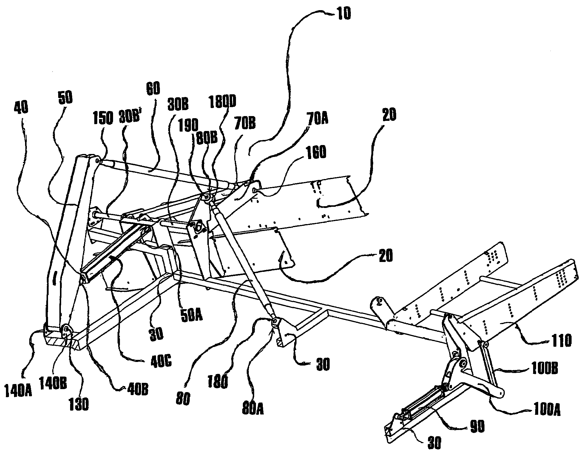
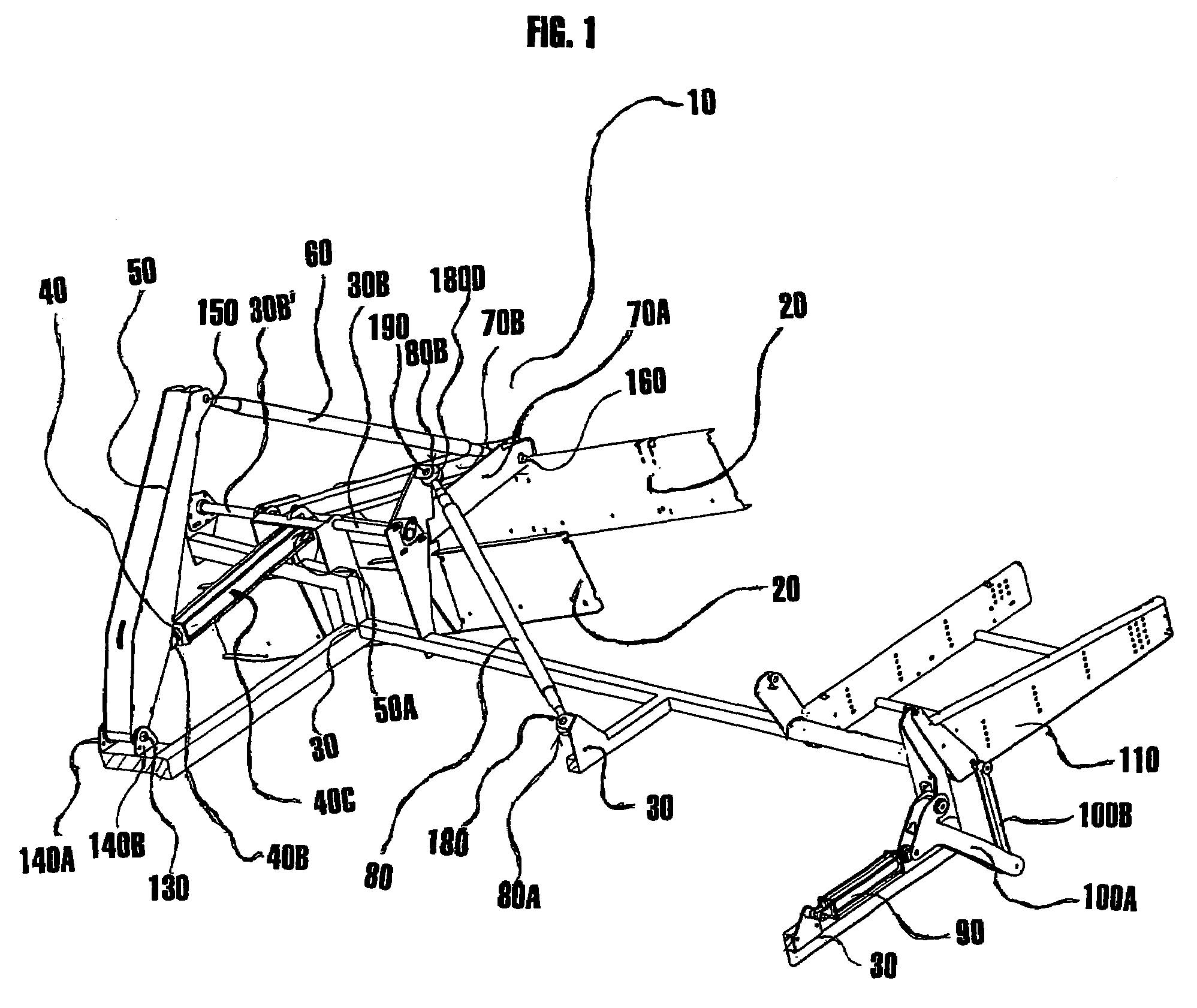
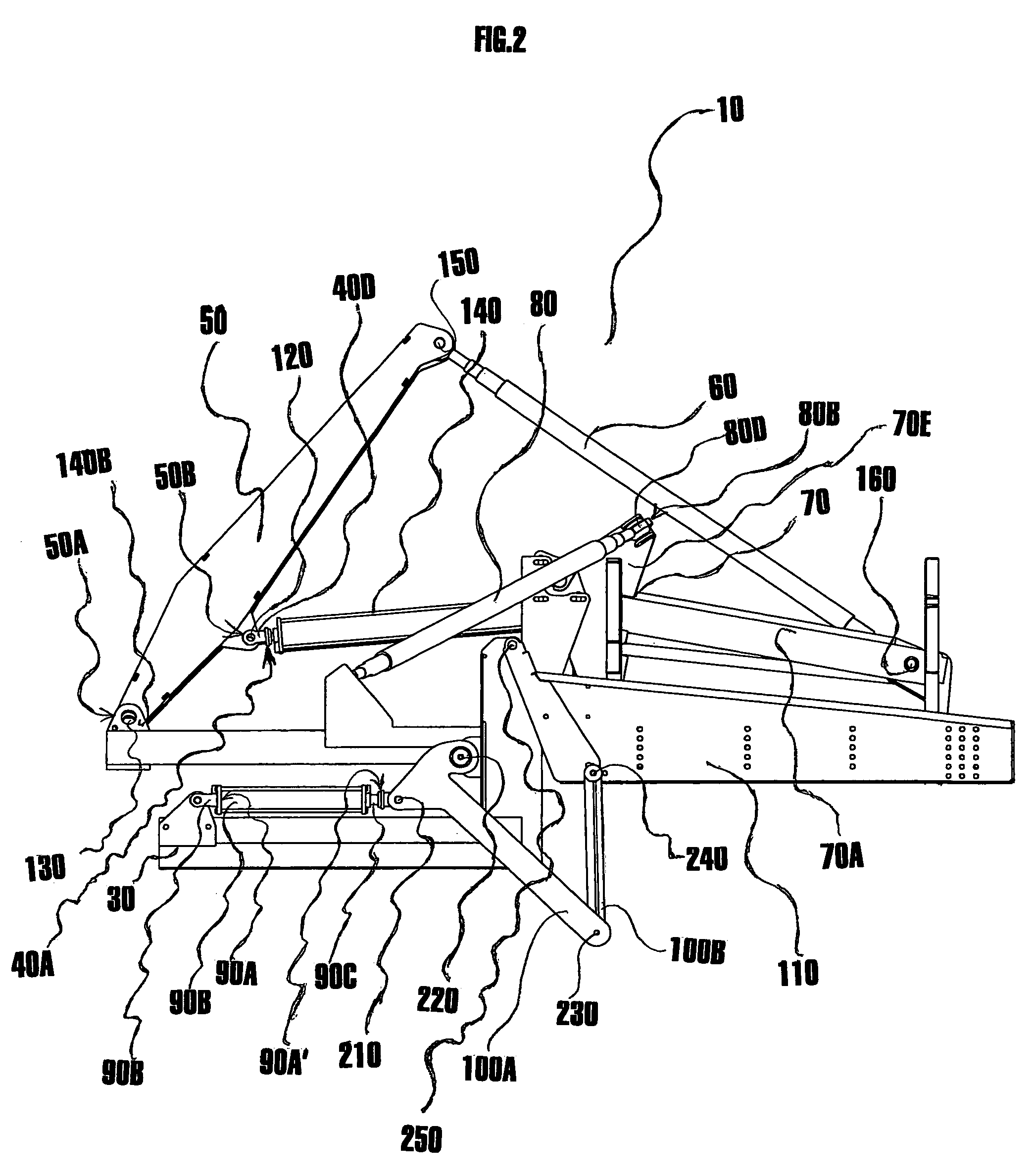
[0024]FIGS. 1, 2, 3, 4, 5 and 6 illustrate a preferred embodiment of an assembly for moving and rotating a conveyor. In standard operation the assembly 10 is operatively connected to (1) a conveyor frame referred to in general by numeral 20, and particularly, a frame for an endless conveyor attached as an elevator to a harvester and (2) a first frame 30 of the harvester.

[0025]With attention directed to figures FIGS. 1, 2, 3, 4, 5 and 6, it is seen that a preferred embodiment of the assembly 10 includes: (1) an actuator 40 operatively connected proximate a first actuator end 40A to the first frame 30; (2) an arm 50 pivotally connecting proximate a first arm end 50A to the first frame 30 and operatively connecting to the actuator 40 at an intermediate connection area 50B; (3) a support sub-assembly 70 slidingly connected to the first frame 30 and being both rotatable around, and moveable forward and rearward along an axis (the axis being illustrated generally as Z in FIGS. 4, 5 and 6)...


PUM


Abstract

The invention is an assembly for moving and rotating a conveyor from a operational orientation to a transport orientation. The assembly includes: an actuator operatively connecting to a first frame; an arm operatively connecting to the actuator and pivotally connecting to a first frame; a support sub-assembly operatively connected to the first frame and selectively rotatable around an axis and moveable forward and rearward along the axis, the support assembly operatively connecting to a conveyor frame; a first turnbuckle pivotally connected to the arm and to the support sub-assembly; and a second turnbuckle pivotally connected to the first frame and to the support sub-assembly. The assembly may further include a second actuator operatively connected to the first frame and operatively connected through a plurality of pivotally attached connection arms to a hopper.

Description

TECHNICAL FIELD[0001]This invention relates to an assembly for moving and rotating a conveyor. More specifically, the invention relates to an assembly for selectively rotating a conveyor frame, particularly a frame for an endless conveyor attached as an elevator to a potato harvester around an axis from an operational orientation to a folded transport orientation while moving the conveyor frame forward and rearward along the axis.BACKGROUND OF THE INVENTION[0002]Processes for harvesting potatoes are well known. In a typical commercial practice potatoes are removed from the earth by a mechanized harvester having a plurality of hoppers and conveyors that collect, transport and elevate harvested potatoes to an elevated terminal discharge end of a final conveyor, the final conveyor frequently being a boom. The potatoes are then dropped from the terminal discharge end and piled into a mechanized transporter, the transporter frequently being a truck having a bed with a conveyor system the...

Claims


Application Information

Patent Timeline
Patent Type & Authority Patents(United States)
IPC IPC(8): B65G21/10
CPCA01D17/00A01D33/00B65G21/14B65G41/005
Inventor KEMPER, RAINER
Owner SPUDNIK EQUIP
Why Eureka
Try Eureka