
Resorption-controllable medical implants

a technology of medical implants and controllable parts, applied in the field of medical implants, can solve the problems of reducing patient medical expenses and patient productivity loss, and achieve the effect of reducing patient medical expenses and productivity loss, and avoiding pain and suffering

Inactive Publication Date: 2007-08-28
BOSTON SCI SCIMED INC
View PDF31 Cites 32 Cited by
  • Summary
  • Abstract
  • Description
  • Claims
  • Application Information

AI Technical Summary

Benefits of technology

The present invention relates to devices and methods for controlling the in vivo resorption of medical implants. The invention provides a medical implant that can be removed from the body of a mammal by natural biological mechanisms, such as by resorption of the implant material followed by normal elimination in a body fluid such as urine or feces. The invention also provides procedures in which removal of an implant is non-invasive, controllable, and predictable. The medical implant includes a first layer and a second layer disposed relative to the first layer, with the second layer including a second bioresorbable material and resorbable particles of a first kind that are dispersed within the second bioresorbable material. The invention also provides a method for controlled release of a bioactive agent within the body of a mammal. The technical effects of the invention include minimizing patient discomfort and the risk of complications to the patient, reducing medical expenses and lost productivity of the patient, and providing a more efficient and effective means for medical implants.

Problems solved by technology

In addition, a non-invasive removal procedure reduces medical expenses and lost productivity of the patient.

Method used


Image

  • Resorption-controllable medical implants
  • Resorption-controllable medical implants
  • Resorption-controllable medical implants

Examples


example 2

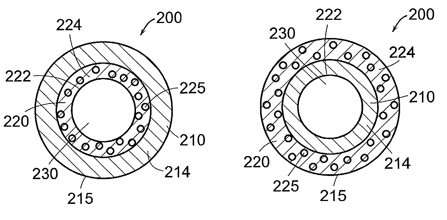
[0076]Paste I and Paste II as prepared in Example 1 are separately placed into two syringes and co-extruded from an extruder to produce a two-layer tube of about 3 mm in diameter and a total wall thickness of about 0.5 mm. The interior layer of the tube consists of Paste II. The exterior layer consists of Paste I. The two-layer tube is extruded directly into a bath including a calcium chloride solution (20% by weight). After about one hour in the bath, the tube was washed with de-ionized water.

example 3

[0077]Example 2 is repeated except that three layers are extruded in making the tube: one interior layer using Paste I, one middle alginate layer using Paste II, and one exterior layer using Paste I. The three-layer tube is about 3 mm in diameter with a wall thickness of about 0.5 mm. The tube is then cut to a length to suit the particular application.

example 4

[0078]Example 2 is repeated except that a predetermined amount of trimethoprim (a anitbacterial agent) is added to Paste I used for extruding the exterior layer to obtain a weight percentage of from about 0.5% to about 30% of the bioactive agent before extrusion of the exterior alginate layer.


PUM

PropertyMeasurementUnit
thicknessaaaaaaaaaa
thicknessaaaaaaaaaa
thicknessaaaaaaaaaa

Abstract

Bioresorbable medical implants are designed to have different resorption rates over time or over the topography of the implants. The resorption of the medical implants are controlled by including layers having differing resorption rates. The layers resorb sequentially over time through sequential exposure to body fluids. A resorption-controllable medical implant includes a series of two or more layers. The first layer includes a first bioresorbable material. The second layer includes a second bioresorbable material and resorbable particles of a first kind dispersed within the second bioresorbable material. Additional layers of bioresorbable material alone or including resorbable particles may be added to slow or speed resorption and achieve desired control over the resorption of the implant. Resorbable particles can be added in differing amounts or kinds in various segments of the implant to provide topographically differing resorption rates.

Description

TECHNICAL FIELD[0001]This invention generally relates to medical implants. More particularly, the invention relates to resorption-controllable medical implants and methods for controlled resorption in the body of a mammal.BACKGROUND INFORMATION[0002]Medical implants have a variety of applications including kidney drainage and vascular surgery. Examples of medical implants include a ureteral stent used for drainage of urine from the kidney to the bladder and a vascular graft used for maintaining blood flow. Medical implants generally have to be removed from the body by an invasive procedure. Medical implants that are left in vivo may cause complications such as inflammation and other foreign body responses.SUMMARY OF THE INVENTION[0003]Medical implants with in vivo controllable resorption are therefore desired. In accordance with the invention, a medical implant is removed from a patient's body by non-invasive means, such as by degradation and resorption of the medical implant by nat...

Claims


Application Information

Patent Timeline
Patent Type & Authority Patents(United States)
IPC IPC(8): A61F2/06A61F2/02A61L27/34A61L27/44A61L27/58A61L29/08A61L29/12A61L29/14A61L29/18A61L31/10A61L31/12A61L31/14A61L31/18A61M25/00
CPCA61L27/34A61L27/44A61L27/58A61L29/085A61L29/126A61L29/148A61L29/18A61L31/10A61L31/125A61L31/148A61L31/18A61M25/0045
Inventor GELLMAN, BARRY N.LI, JIANMIN
Owner BOSTON SCI SCIMED INC
Learn More