

Circuit and method for controlling DC-DC converter
a technology of dc-dc converter and control circuit, which is applied in the direction of electric variable regulation, process and machine control, instruments, etc., can solve the problem that the conventional configuration fails to suppress the generation of inrush current during the activation of dc-dc, and achieve the effect of suppressing the generation of inrush curren
- Summary
- Abstract
- Description
- Claims
- Application Information
AI Technical Summary
Benefits of technology
Problems solved by technology
Method used
Image

Examples
first embodiment
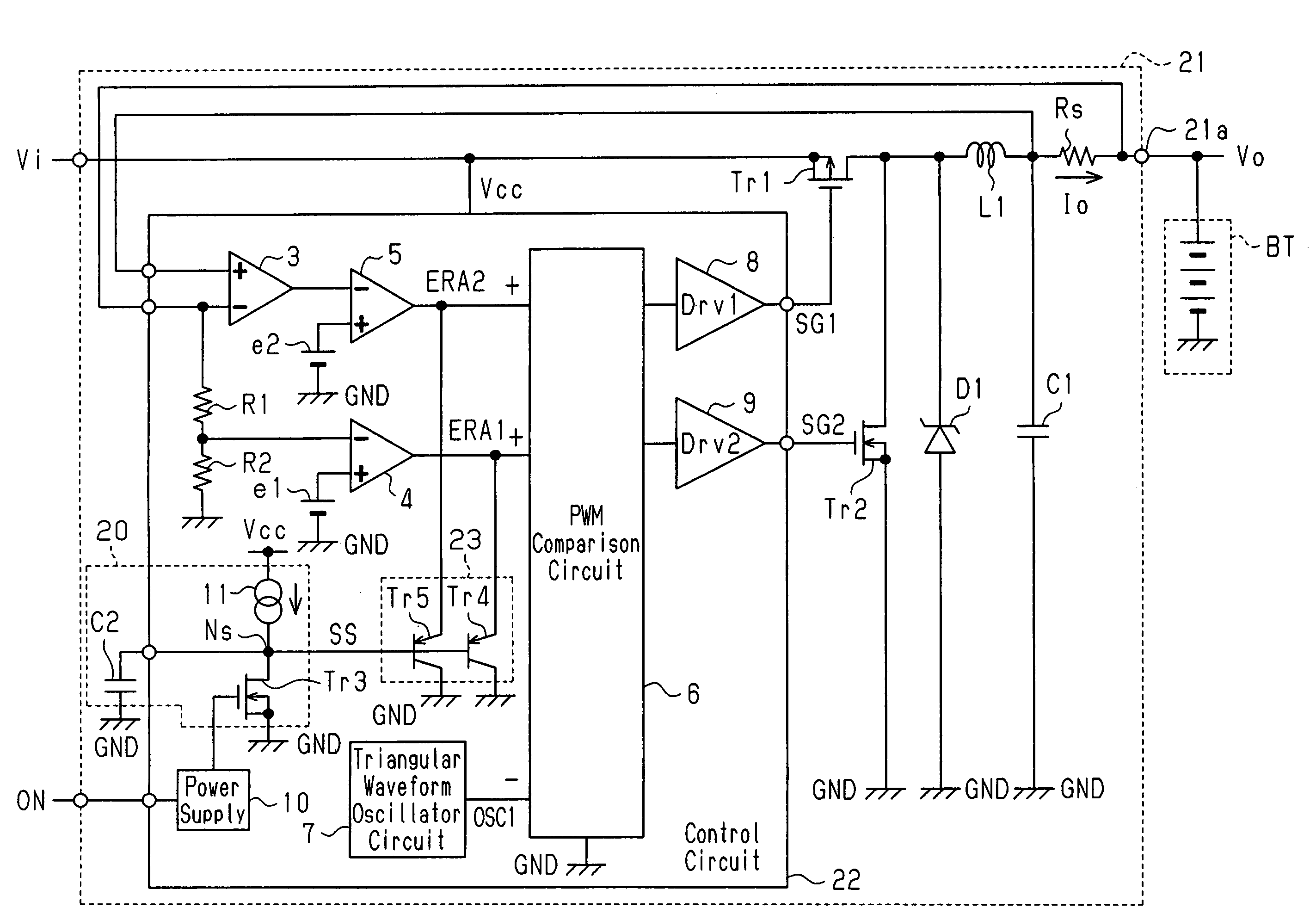
[0060]A DC-DC converter 21 and an electronic device 12 according to a first embodiment of the present invention will now be described with reference to FIGS. 5 to 7.
[0061]FIG. 7 is a schematic block diagram of the electronic device 12. The electronic device 12 is, for example, a portable electronic device, such as a notebook personal computer. The electronic device 12 has a connection terminal 14, which is connected to an AC adaptor 13 and is supplied with direct current input voltage Vi from the AC adaptor 13.
[0062]The electronic device 12 includes an internal circuit 15, a battery BT, the DC-DC converter 21, and diodes D2 and D3. The battery BT includes a plurality of secondary batteries. The battery BT supplies the internal circuit 15 with operation power supply voltage when the AC adaptor 13 is not connected to the electronic device 12. The internal circuit 15 provides various functions to the user of the electronic device 12. The DC-DC converter 21 functions as a charging circu...
second embodiment
[0097]A DC-DC converter 31 according to a second embodiment of the present invention will now be described with reference to FIG. 8.
[0098]The DC-DC converter 31 of the second embodiment shown in FIG. 8 differs from the DC-DC converter 21 of the first embodiment in that a clamp circuit (specifically clamp elements forming the clamp circuit) is configured by diodes D4 and D5 in a control circuit 32. The other components of the DC-DC converter 31 are the same as the corresponding components in the first embodiment.
[0099]The diodes D4 and D5 are Schottky barrier diodes in the second embodiment. The cathode of each of the diodes D4 and D5 (clamp elements) is connected to the connecting node Ns between the constant current circuit 11 and the transistor Tr3. The anode of the diode D4 is connected to the output terminal of the first error amplification circuit 4. The anode of the diode D5 is connected to the output terminal of the second error amplification circuit 5.
[0100]During activation...
third embodiment
[0101]A DC-DC converter 41 according to a third embodiment of the present invention will now be described with reference to FIG. 9.
[0102]The DC-DC converter 41 of the third embodiment shown in FIG. 9 is configured by changing the voltage step-down configuration of the DC-DC converter 31 in the second embodiment (refer to FIG. 8) to a voltage step-up / step-down configuration. The other components of the DC-DC converter 41 are the same as the corresponding components in the second embodiment.
[0103]In detail, the DC-DC converter 41 of the third embodiment includes, in addition to the components of the DC-DC converter 31 of the second embodiment, transistors Tr6 and Tr7 and third and fourth output circuits 43 and 44 (Drv3 and Drv4). The third output circuit 43 is connected to the PWM comparison circuit 6 and the transistor Tr6. The third output circuit 43 controls on and off of the transistor Tr6 according to output pulses of the PWM comparison circuit 6. The fourth output circuit 44 is ...
PUM
 Abstract
Description
Claims
Application Information