Radio communication device and arrival direction estimation method

a radio communication device and arrival direction technology, applied in the direction of multi-channel direction-finding systems using radio waves, dc level restoring means or bias distorting correction, instruments, etc., can solve the problem of deteriorating receiving quality, inability to secure estimation accuracy per path, interference of radio communication devices, etc. problem, to achieve the effect of reducing throughput and stable accuracy

Active Publication Date: 2007-08-28
PANASONIC CORP
View PDF20 Cites 34 Cited by
  • Summary
  • Abstract
  • Description
  • Claims
  • Application Information

AI Technical Summary

Benefits of technology

[0033]The present invention is also provided with an arrival direction estimation method that collectively estimates multiple path arrival directions by receiving multiple I/Q baseband signals obtained by frequency-converting multiple high frequency signals that are received by an array antenna composed of multiple antenna elements and orthogonally detecting them respectively by multiple radio receiving units, calculating a correlation operation value with known signals at each of detected multiple arrival path receiving timings, obtaining one angular spectrum using a path correlation value synthesis signal with which the calculated multiple correlation operation values are synthesized and detecting a peak location and a peak

Problems solved by technology

The signal a radio communication device receives is interfered with various signals and deteriorates receiving quality.
Consequently, since the time resolution of an arrival path increases and the electric power per path decreases, such a problem that the arrival direction estimation accuracy per path cannot be secured is caused.
When a comm

Method used


Image

  • Radio communication device and arrival direction estimation method
  • Radio communication device and arrival direction estimation method
  • Radio communication device and arrival direction estimation method

Examples


embodiment 1

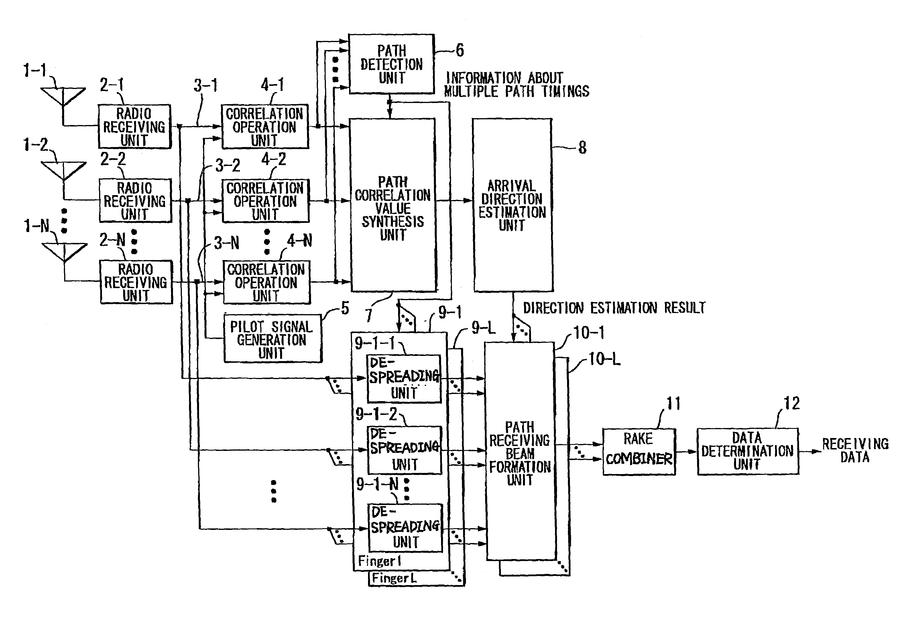
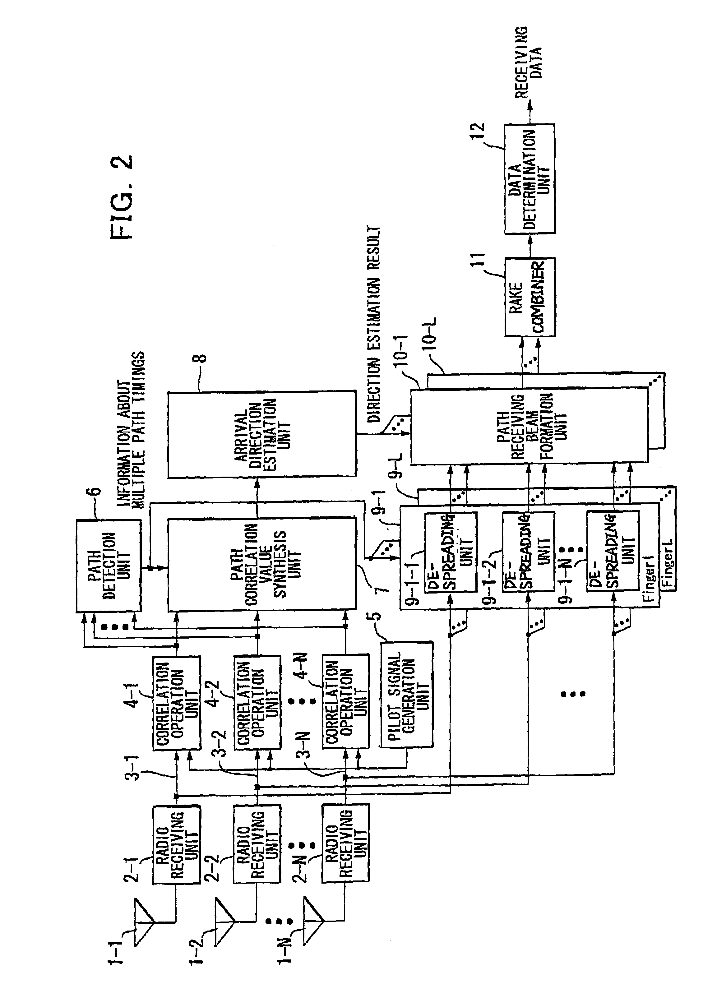
[0044]FIG. 2 is a block diagram showing the configuration of a radio communication device according to an embodiment 1 of the present invention. The radio communication device shown in FIG. 2 applies high frequency amplification, frequency conversion, orthogonal detection and A / D conversion sequentially to high frequency signals received by antenna elements 1-1 to N constructing an array antenna 1 in radio receiving units 2-1 to N installed in each of the antenna elements 1-1 to N, and generates baseband signals 3-1 to N composed of signals I and Q. However, N is the number of antenna elements.

[0045]The baseband signals 3-1 to N are input to each of correlation operation units 4-1 to N in response to each signal respectively. A pilot signal generation unit 5 generates a known signal (hereinafter referred to as a pilot signal) embedded previously in a receiving signal. The correlation operation units 4-1 to N perform a mutual correlation operation with the pilot signal. For example, ...

embodiment 2

[0070]FIG. 4 is a block diagram showing the configuration of forming sending directivity adaptively based on the result of the arrival direction estimation unit 8 according to Embodiment 1. The part that differs from Embodiment 1 is mainly described below.

[0071]The operation until a direction estimate is obtained in the arrival direction estimation unit 8 based on a receiving signal by the array antenna 1 is the same as Embodiment 1. In this embodiment, the operation of the arrival direction estimate unit 8 is performed as a different operation, that is, 1) when all path arrival directions are estimated in the common direction θs and 2) multiple arrival direction estimates are output.

[0072]A modulation unit 20 modulates sending data into a predetermined modulation format. A sending beam formation unit 21 distributes the output of the modulation unit 20 into the number that is equal to the number of elements N of the array antenna 1 and multiplies each output by the elements of sendi...

embodiment 3

[0082]FIG. 5 is a block diagram showing the configuration of a radio communication device that adds an arrival direction estimation unit 30 per path that estimates a path arrival direction in a different path receiving timing individually to the arrival direction estimation unit 8 described in Embodiment 1 and forms and receives a path receiving beam using one of these direction estimation results selectively.

[0083]Since the operation of the arrival direction estimation unit 8 is the same as that of Embodiment 1, a description will be mainly made of the operation of a newly added arrival direction estimation unit 30 per path, an angular spread calculation unit 31 that calculates an angular spread based on the direction estimation result for every path and an arrival direction estimation system selection unit 32 that selects either of the estimation result of the arrival direction estimation unit 8 or that of the arrival direction estimation unit 30 per path based on the detection re...


PUM


Abstract

A receiver having an array antenna estimates arrival directions of multiple paths that arrive with an angular spread. Consequently, arrival direction estimation accuracy can be ensured without increasing throughput even if the power every path is low by estimating an average arrival direction of an entire set of multiple paths having the angular spread from a result of one angular spectrum by multiple correlation operation units that perform mutual correlation operations with pilot signals for baseband signals received by the array antenna, a path detection unit that detects multiple arrival path receiving timings by generating a delay profile based on output of each of the correlation operation units, a path correlation value synthesis unit that synthesizes a correlation operation value calculated in the multiple correlation operation units and an arrival direction estimation unit that collectively estimates multiple path arrival directions using output of the path correlation value synthesis unit.

Description

BACKGROUND OF THE INVENTION[0001]1. Field of the Invention[0002]The present invention relates to an arrival path direction estimation means in a radio communication device having an array antenna used in a digital radio communication system and a directional control means based on the arrival path direction estimation means.[0003]2. Description of Prior Art[0004]The signal a radio communication device receives is interfered with various signals and deteriorates receiving quality. An adaptive array antenna is known as an art that suppresses this interference and powerfully receives only the signal arriving from a desired direction. The adaptive array antenna can powerfully receive only the signal arriving from the desired direction by adjusting a weighting coefficient multiplying a receiving signal (hereinafter, this weighting coefficient is referred to as ‘weight’) and adjusting an amplitude and a phase applied to the receiving signal.[0005]Further, the radio communication device re...

Claims


Application Information

Patent Timeline
IPC IPC(8): H04B7/216H01Q3/26G01S3/74H04B1/707H04B7/06H04B7/08H04B7/26H04L1/06
CPCG01S3/74H04B1/7113H04B7/086H04L1/06H04B1/7117H04B7/0617H04B2201/70701H04B2201/70715
Inventor KISIGAMI, TAKAAKIFUKAGAWA, TAKASHIYUDA, YASUAKITAKAUSAKI, KEIJIMIYAMOTO, SHOJI
Owner PANASONIC CORP
Why Eureka
Try Eureka