Apparatus for measuring intravascular blood flow

a technology for intravascular blood flow and measuring apparatus, which is applied in the field of measuring intravascular blood flow, can solve the problems of not being able to precisely not being able to accurately measure the distance between the point of saline injection and the patient's blood stream, and not being able to accurately measure the distance between the point of saline injection and the sensor. , to achieve the effect of improving the accuracy of blood

Active Publication Date: 2007-08-28
CORAL SAND BEACH LLC
View PDF9 Cites 79 Cited by
  • Summary
  • Abstract
  • Description
  • Claims
  • Application Information

AI Technical Summary

Benefits of technology

[0006]Another object of the invention is to provide such a method which avoids the use of conventional temperature sensors such as thermisters, thermocouples and the like.
[0007]Another object of the invention is to provide a flow rate measuring method which does not require the introduction of a foreign fluid into the patient's blood stream.

Problems solved by technology

In some situations, it may not be desirable to inject saline solution into the patient's blood stream.
In addition, the distance between the point of saline injection and the sensor is not always known exactly.
Those prior flow rate measuring devices which utilize temperature sensors such as thermisters and the like are also disadvantaged in that the sensors are not particularly sensitive and require recalibration because their thermal resistive characteristics may change over time.

Method used


Image

  • Apparatus for measuring intravascular blood flow
  • Apparatus for measuring intravascular blood flow

Examples


Embodiment Construction

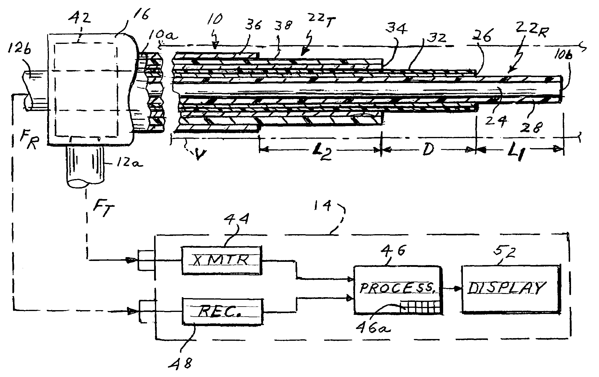
[0017]Referring to FIG. 1 of the drawing, the present apparatus comprises a flexible catheter shown generally at 10 for insertion into a blood vessel V. Catheter 10 is connected by coaxial cables 12a and 12b to a control unit 14. The catheter has a proximal end 10a to which cables 12a and 12b are connected by way of a fitting or connector 16 and a distal end or tip 10b. In a typical procedure, the catheter may be inserted into the patient through a standard introducer inserted in the patient's neck. The introducer is typically 8.5 French, which the catheter may be 6 or 7 French. The catheter 10 goes from the jugular through the right side of the heart and then into the pulmonary artery.

[0018]As shown in FIG. 1, catheter 10 incorporates coaxial inner and outer antennas 22R and 22T. The inner antenna 22R comprises a coaxial cable consisting of an inner conductor 24 and an outer conductor 26 separated by a dielectric layer 28, the outer conductor 26 being surrounded by a thin dielectri...


PUM


Abstract

Microwave apparatus for measuring the blood flow rate in a patient's blood vessel includes an intravascular catheter having proximal and distal ends and containing an inner coaxial cable forming a first antenna and an outer cable coaxial with the inner cable and forming a second antenna, the first antenna extending axially beyond the second antenna a selected distance. The apparatus also includes a control unit including a microwave transmitter, a microwave receiver and a processor controlling the transmitter and receiver. A diplexer is connected between the first and second antenna and the control unit to couple signals from the transmitter to the second antenna but not to the receiver and to couple signals from the first antenna to the receiver but not to the transmitter. The transmitter transmits microwave pulses to the first antenna which heat blood around that antenna. When the heated blood volume flows to the second antenna this is detected at the receiver which produces a detect signal. The processor measures the time interval between each pulse a subsequent detect signal and divides that time interval into the axial distance between the two antennas to compute the flow rate.

Description

[0001]This invention relates to the measurement of intravascular blood flow. It relates especially to a method and apparatus for measuring such flow utilizing microwave radiometry.BACKGROUND OF THE INVENTION[0002]There are many instances when it is desirable or necessary to know the rate of flow of blood through a particular blood vessel of a patient for diagnostic purposes and in preparation for a surgical procedure. This flow rate may vary due to various factors such as the patient's blood pressure, presence of arthroscopic plaques which may partially occlude a blood vessel, etc.[0003]The conventional method of measuring blood flow utilizes so-called thermodilution. An intravascular catheter carrying a temperature sensor such as a thermister or thermocouple is introduced into the pulmonary artery. Then saline is injected into the right atrium or ventricle to allow proper mixing of saline in the blood. Sometimes the saline is a room temperature but more often it is at a lower tempe...

Claims


Application Information

Patent Timeline
Patent Type & Authority Patents(United States)
IPC IPC(8): A61B5/027A61B5/028
CPCA61B5/027A61B5/0507A61B5/028
Inventor CARR, KENNETH L.
Owner CORAL SAND BEACH LLC
Why Eureka
Try Eureka