Heat exchanger apparatus and method for evaporative cooling refrigeration unit

a technology of heat exchanger and refrigeration unit, which is applied in the direction of indirect heat exchanger, domestic cooling apparatus, lighting and heating apparatus, etc., can solve the problems of relative inefficiency in cooling the condenser coil, evaporation of water and air cooling, and achieve enhanced heat transfer and improved heat transfer

Inactive Publication Date: 2007-09-04
EP INVESTMENTS INC THROUGH ITS CHAPTER 7 TRUSTEE
View PDF11 Cites 36 Cited by
  • Summary
  • Abstract
  • Description
  • Claims
  • Application Information

AI Technical Summary

Benefits of technology

[0016]As the water travels down the condenser coils ambient air is pulled across by a fan to further cool the condenser coils and evaporate some water to provide cooling. The evaporative fill in front of or behind the condenser coils also help to cool the coils by directing the air flow through and on to the condenser coils. The evaporative fill also cools the water to provide cooler water to the sump, which in turn provides better heat transfer from the coils to the water.

Problems solved by technology

The problem with these units is that they can be relatively inefficient in cooling the condenser coils, particularly as the ambient temperature rises.
A fan draws air into the inlet duct and through the air, which results in evaporation of the water and cooling of the air.

Method used


Image

  • Heat exchanger apparatus and method for evaporative cooling refrigeration unit
  • Heat exchanger apparatus and method for evaporative cooling refrigeration unit
  • Heat exchanger apparatus and method for evaporative cooling refrigeration unit

Examples


Embodiment Construction

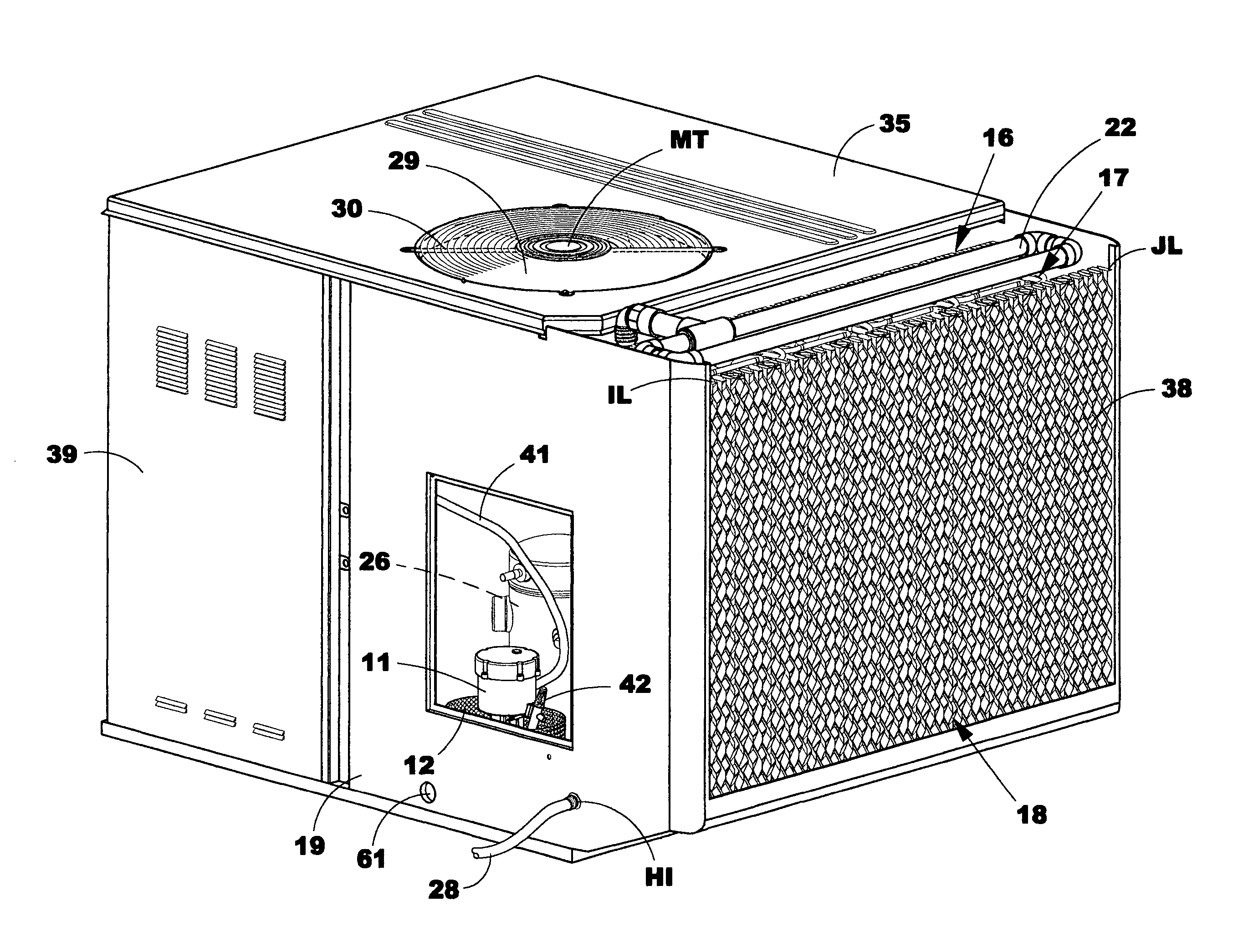
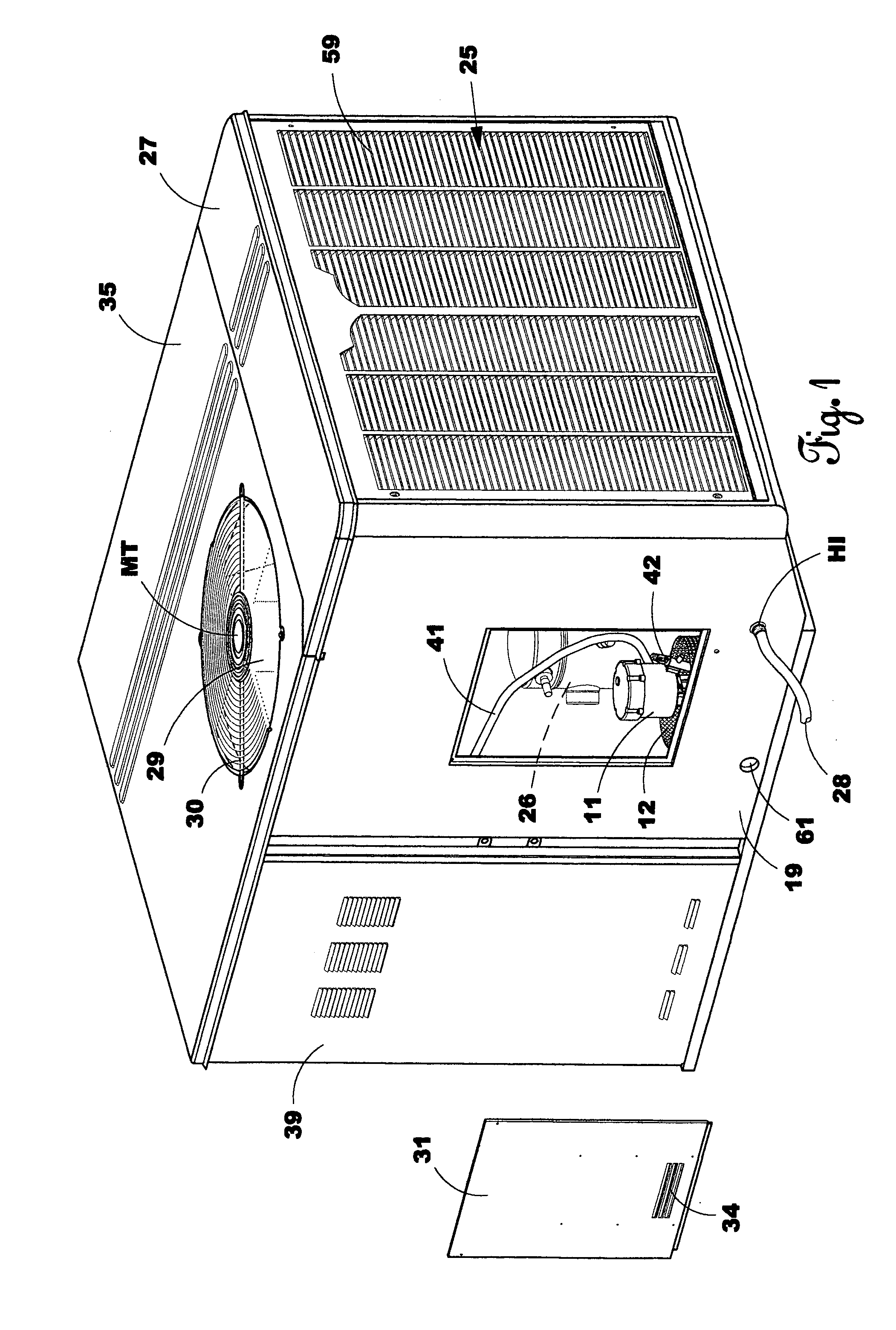
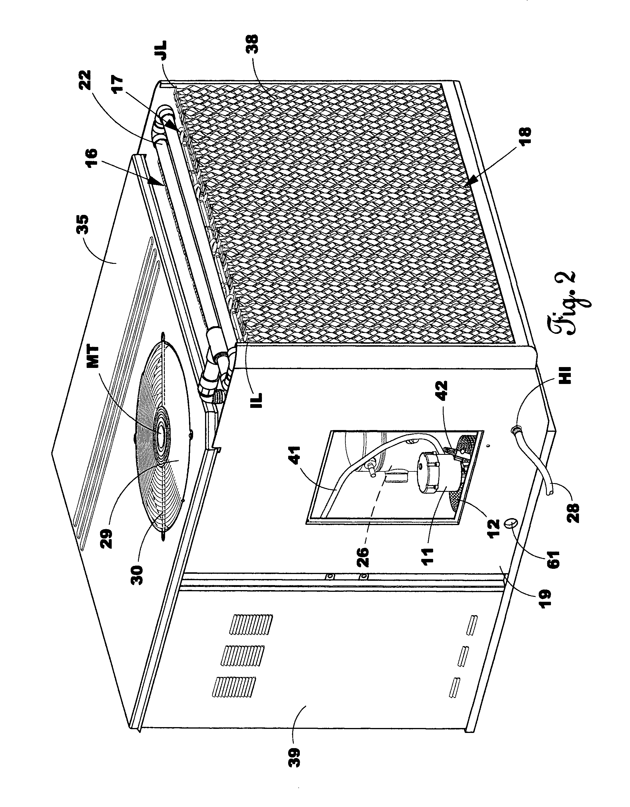
[0035]The invention includes an air conditioning unit means 10 (FIG. 1). The operation of water cooled air conditioners is disclosed in detail in my U.S. Pat. No. 5,832,739 and U.S. Pat. No. 5,992,171 which are incorporated here in by this specific reference thereto.

[0036]An embodiment of the invention is accomplished by retrofitting an existing air conditioning unit with the water cooled condenser components and to the specifications set out below. For example a standard York brand air cooled air conditioning unit may be used by removing the standard air cooled condensing coils of that unit and then substituting the water cooled condenser components of this invention. This enables the use of a mass produced standard air conditioning unit rather than constructing a new unit from the ground up to greatly reduce costs. Furthermore, repair persons are familiar with the standard air cooled unit and only need to also learn the added water cooled condensing components. After the component...


PUM


Abstract

This invention is for a highly efficient heat transfer unit and method for heat transfer for an air conditioning refrigeration unit. The invention has a plurality of condenser coils that stand generally vertically upright (with up to 20° tilt to optimize downward water flow with air being pulled across) between a splash louver and an evaporative fill material. The evaporative fill material and the splash louver transfer heat from the water by air cross flow to make the air conditioning unit very efficient and reduces the amount of copper coils needed. The condenser coils are cooled by water flowing down through them and into a sump. The condenser coils are also cooled by air pulled across them by a fan mounted on the top of the air conditioning unit. The sump in the bottom of the unit has a wall that directs the water in it to a water pump that then sends the water to the water distribution pipe. The water pipe covers the water distribution member with water, which then allows the water to flow down the condenser coils. The large amount of heat that is transferred from the condenser coils to the water and the air cross flow is what enables the air conditioning unit to be so efficient. A low pressure drop of refrigerant in the condensing coils, the large surface area, and horizontal air flow also helps the air conditioning unit to be efficient.

Description

CROSS-REFERENCE TO RELATED APPLICATIONS[0001]NoneSTATEMENTS REGARDING FEDERALLY SPONSORED RESEARCH OR DEVELOPMENT[0002]NoneREFERENCE TO A MICROFICHE APPENDIX[0003]NoneBACKGROUND OF THE INVENTION[0004]1. Field of the Invention[0005]The invention relates to a water cooled air conditioner having a heat exchanger for an air conditioner refrigeration unit using water and air to cool the hot refrigerant in the condenser coils and a method for transferring heat from said condenser coils.[0006]2. Description of the Related Art[0007]In prior art air conditioners the condenser coils have been typically cooled in an air conditioner refrigeration system by pulling ambient air across the condenser coils with a fan inside the unit. The problem with these units is that they can be relatively inefficient in cooling the condenser coils, particularly as the ambient temperature rises. As the ambient temperature rises the efficiency rating goes down. When the ambient temperature is very hot, the effici...

Claims


Application Information

Patent Timeline
Patent Type & Authority Patents(United States)
IPC IPC(8): F28D5/00
CPCF25B39/04F28D5/02F25B2339/041
Inventor BACCHUS, ROCKNEY D.
Owner EP INVESTMENTS INC THROUGH ITS CHAPTER 7 TRUSTEE
Why Eureka
Try Eureka