Joystick for electro-hydraulic control system

a control system and electrohydraulic technology, applied in the direction of mechanical control devices, gearing, instruments, etc., can solve the problems of deterioration of output characteristics, and possible breakage of the coil portion 21/b>, so as to avoid any substantial displacement of the pivotable arm, inhibit abrasion, and high accuracy

Active Publication Date: 2007-09-04
NIHON KENKI CO LTD
View PDF9 Cites 22 Cited by
  • Summary
  • Abstract
  • Description
  • Claims
  • Application Information

AI Technical Summary

Benefits of technology

[0027]The present invention has been completed in view of the above-mentioned actual situation of the conventional art. An object of the present invention is, therefore, to provide a joystick for an electro-hydraulic control system, which is provided with a torsion coil spring to normally hold neutral a pivotable arm arranged on a rotary potentiometer and allows the pivotable arm to surely return to the original neutral position to which the pivotable arm is supposed to return.
[0043]As has been described above, the torsion coil spring which holds the pivotable arm in the neutral position returns to the correct neutral position by the limiting means when the control member is controlled back from a controlled position to the neutral position. The present invention, therefore, allows the pivotable arm of the rotary potentiometer, said pivotable arm being in engagement with the torsion coil spring, to surely return to the original neutral position without any substantial inclination.
[0045]In the present invention as described above, the cover member can preferably be made of a metallic material, and the guide portions preferably can have been formed by bending. The present invention constructed as described above makes it possible to form the pair of guide portions by simply bending the cover member, and therefore, the fabrication of the guide portions is simple.
[0059]In the present invention constructed as described above, control of the control member from its neutral position causes the extension arm to pivot about the support pin. As a result, the pivotable arm of the rotary potentiometer pivots, and the rotary shaft arranged integrally with the pivotable arm rotates. As a result, a rotation angle signal corresponding to the stroke of the control member is outputted. In the meantime, the arm portion of the torsion coil spring is caused to expand by a rotary member which constitutes the expanding means. As a result of the expansion of the arm portions of the torsion coil spring, the rotary member maintained in contact with the arm portion rotates. It is, therefore, possible to inhibit the occurrence of abrasion between the rotary member and the arm portions of the torsion coil spring, which would otherwise take place as a result of repeated pivotal control of the control member.
[0065]Owing to the arrangement of the means for limiting movements of the coil portion of the torsion coil spring at its neutral position in the predetermined direction and the opposite direction, the present invention allows the pivotable arm, to which the torsion coil spring is brought into engagement, of the rotary potentiometer to surely return to the original neutral position. It is, therefore, possible to avoid any substantial displacement of the pivotable arm from its original neutral position when the control member is controlled back to its neutral position. Accordingly, output characteristics of high accuracy can be obtained compared with the conventional art.
[0066]In the present invention, the rotary member rotates when the arm portions of the torsion coil spring are caused to expand by a pivotal movement of the pivotable arm of the rotary potentiometer as a result of pivotal control of the control member. Owing to the above-mentioned rotation of the rotary member, it is, therefore, possible to inhibit the abrasion between the rotary member and the arm portions of the torsion coil spring that would otherwise take place as a result of repeated pivotal control of the control member. The rotary member and the arm portions of the torsion coil spring can, therefore, be maintained in their deformation-free, original forms over a long term, so that the pivotable arm, with which the torsion coil spring is brought into engagement, of the rotary potentiometer is allowed to surely return to the original neutral position. In other words, it is possible to avoid any substantial displacement of the pivotable arm from its original neutral position when the control member is controlled back to its neutral position, thereby making it possible to obtain output characteristics of high accuracy compared with the conventional art.

Problems solved by technology

As a result, the coil portion 21c progressively cinches up the holding pin 30, and therefore, an excessive tensile force acts on the coil portion 21c, leading to a potential problem that the coil portion 21 may be broken.
As a consequence, upon controlling back the control lever to the neutral position, a displacement takes place relative to the original neutral position to which the pivotable arm 14 is supposed to return, thereby developing a problem that deteriorations take place in output characteristics.
The conventional art, therefore, involves the problem that, when the control lever is controlled back to the neutral position, the abrasion causes a displacement relative to the original neutral position to which the pivotable arm 14 is supposed to return and the displacement leads to deteriorations in output characteristics.

Method used


Image

  • Joystick for electro-hydraulic control system
  • Joystick for electro-hydraulic control system
  • Joystick for electro-hydraulic control system

Examples


first embodiment

[0085][Basic Construction of the First Embodiment]

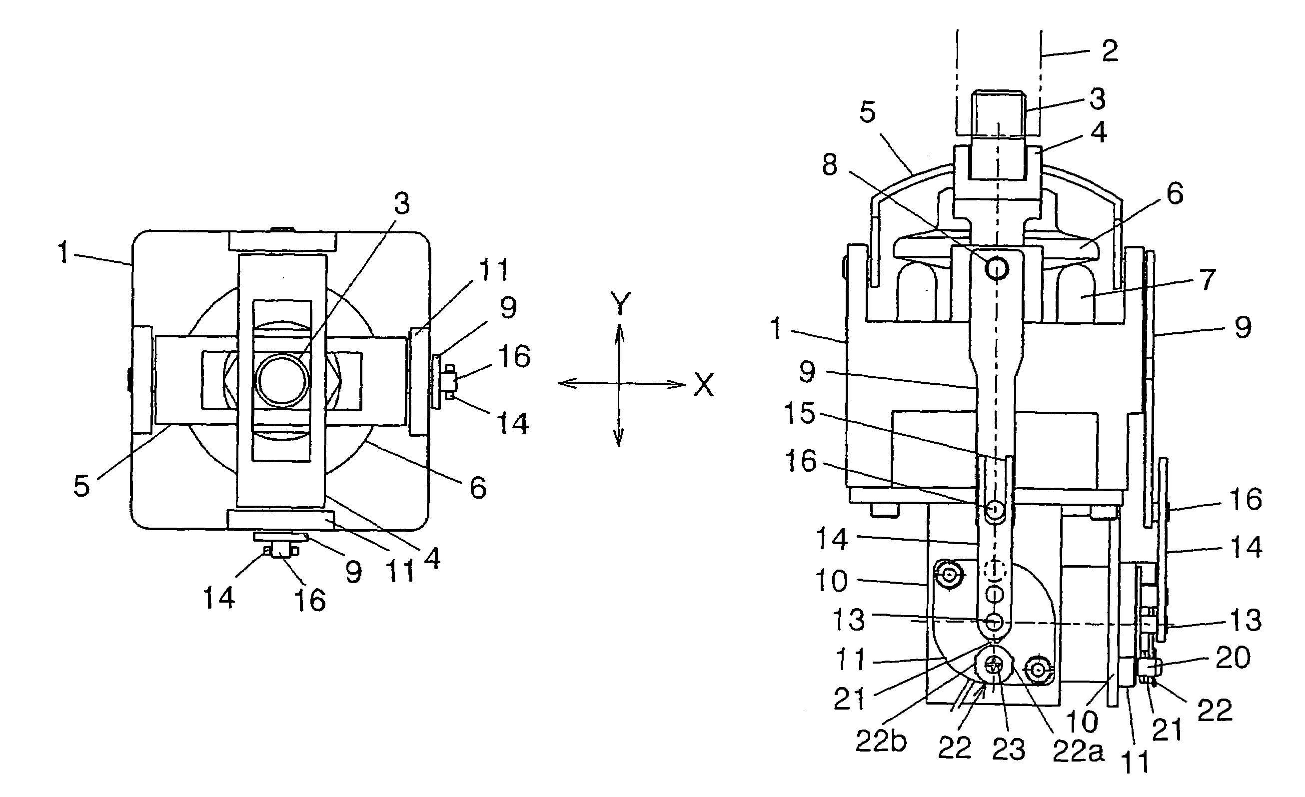
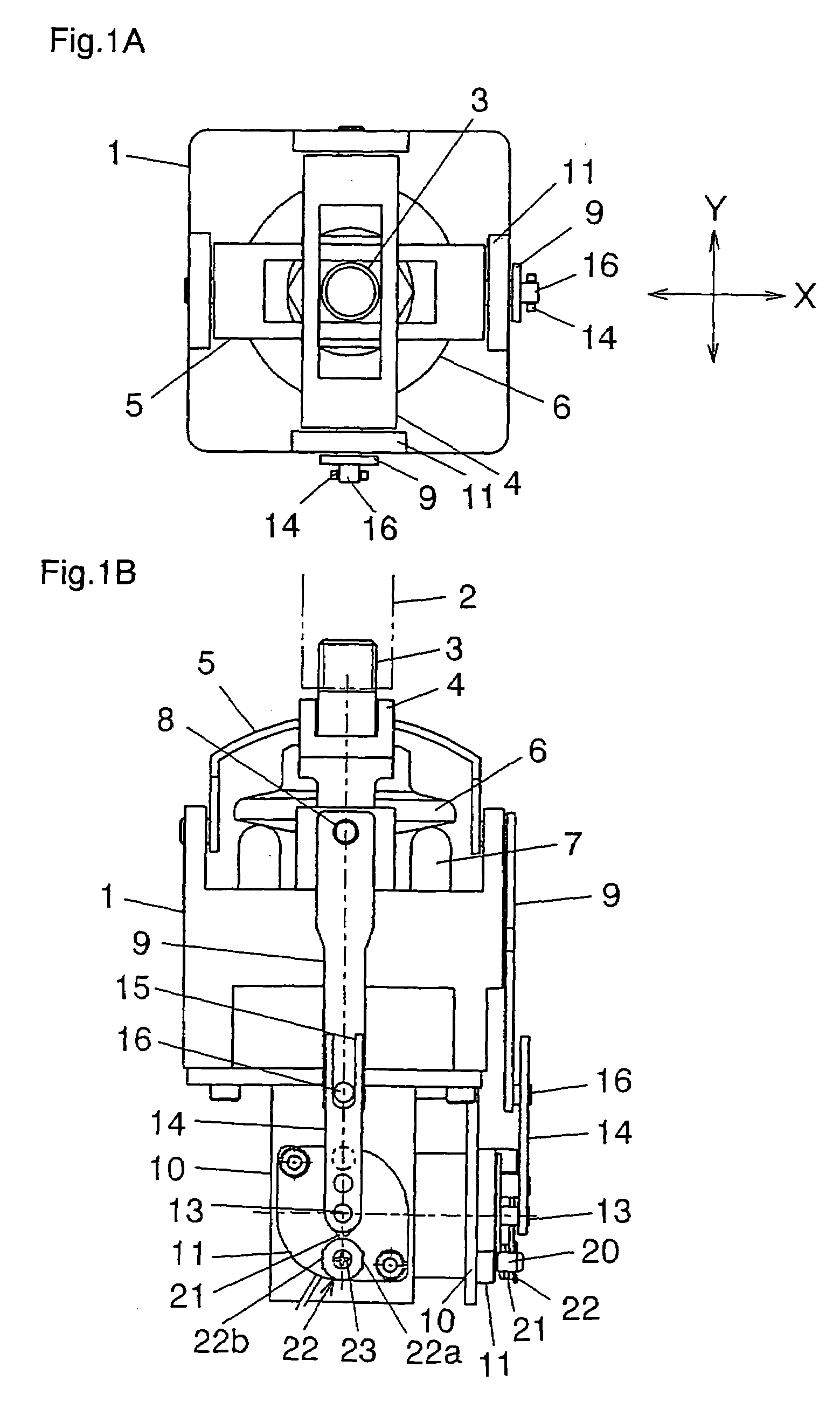
[0086]Firstly, the joystick according to the first embodiment of the present invention for the electro-hydraulic control system will be described with reference to FIGS. 1A through 3C. The joystick of the first embodiment is used, for example, as a joystick for controlling various hydraulic cylinders or hydraulic actuators, such as hydraulic motors, arranged in a hydraulic excavator. As illustrated in FIGS. 1A and 1B, the joystick of the first embodiment is provided with a housing main body 1 for a control lever unit, a control member, for example, a control lever 2 pivotally controlled by an operator, a universal joint 3 connected with the control lever 2, a first gymbal 4 rockably supported on the housing main body 1 and rockable as a result of pivotal control of the control lever 2, for example, in a direction X, a second gymbal 5 arranged extending in a direction which intersects at right angles with a direction in which the firs...

second embodiment

[Basic Construction of the Second Embodiment]

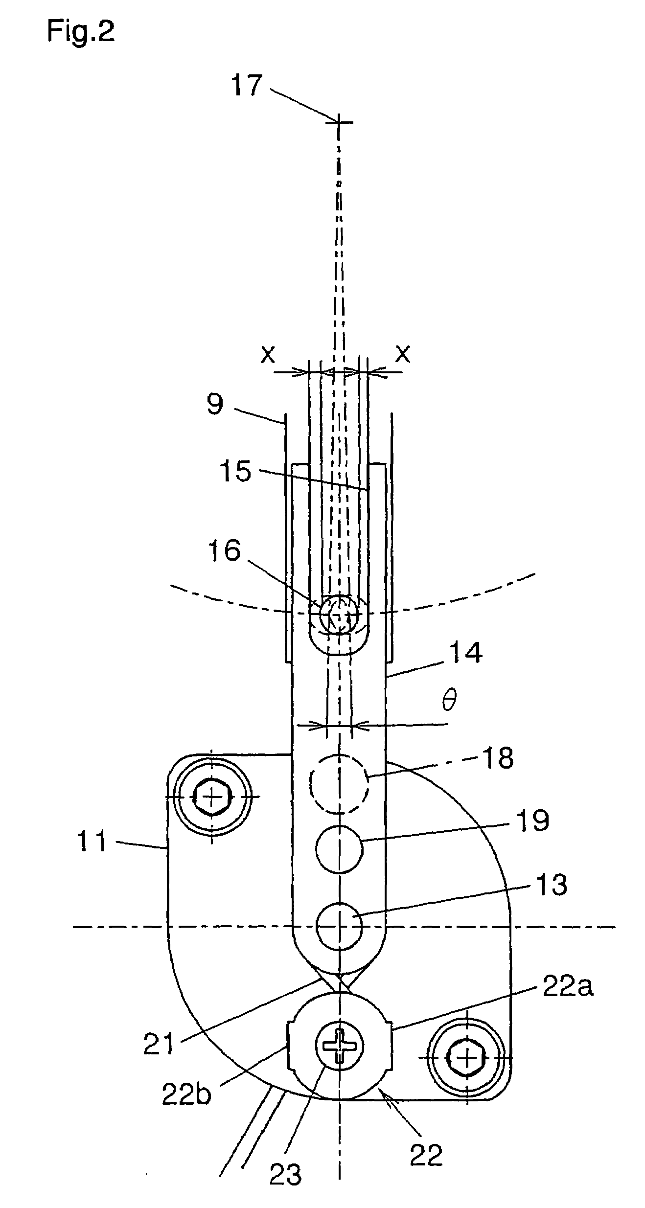
[0106]The joystick according to the second embodiment of the present invention for the electro-hydraulic control system will next be described with reference to FIGS. 6A through 8. It is to be noted that the basic construction itself is similar to that described with reference to FIG. 1A through FIG. 3C except for the construction of the cover member 22 and the construction around the rotary shaft 13 of the pivotable arm 14, overlapping descriptions will be omitted and only different features will be described.

[0107]This embodiment is different from the first embodiment in that as illustrated in FIGS. 6A and 6B, the cover member 22 is not provided with the guide portions 22a, 22b, the stopper 18 and the like are modified, and a pin portion 30 and a bearing 31 are arranged. Details will be mentioned next.

[Construction of Essential Part of the Second Embodiment]

[0108]As shown in FIG. 7A through FIG. 8 and the like, this embodiment is equipp...

third embodiment

[0118]The joystick according to the third embodiment of the present invention for the electro-hydraulic control system will next be described with reference to FIGS. 11A and 11B.

[0119]The third embodiment illustrated in FIGS. 11A and 11B has a construction that a stopper 32 for limiting movements of the arms 21a, 21b of the torsion coil spring 21 at its neutral position is arranged on the pivotable arm 14 of the rotary potentiometer 11 and a rotary member, for example, a bearing 34, which constitutes the expanding means for causing the arms 21a, 21b of the torsion coil spring 21 to expand, is rotatably mounted on a pin portion 33 formed on the housing main body of the rotary potentiometer 11. The remaining construction is similar to that of the above-described second embodiment.

[0120]In the third embodiment constructed as described above, whenever the arm portion 21b or the like of the torsion coil spring 21 is caused to expand by the bearing 34 upon pivotal control of the control l...


PUM


Abstract

A joystick for an electro-hydraulic control system is provided with a rotary potentiometer having a pivotable arm. This pivotable arm is integrally arranged on a rotary shaft and pivots responsive to pivotal control of a joystick in a predetermined direction or a direction opposite to the predetermined direction. The joystick is also provided with a torsion coil spring for normally holding the pivotable arm in a neutral position, a pin arranged on the pivotable arm and capable of expanding the torsion coil spring upon pivotal movement of the pivotable arm, a holding pin for holding the torsion coil spring at its coil portion, and a cover member having a pair of guide portions for limiting movements of the coil portion of the torsion coil spring in the predetermined direction and the opposition direction when the torsion coil spring is in its neutral position.

Description

FIELD OF THE INVENTION[0001]This invention relates to a joystick for electro-hydraulic control system arranged on a hydraulic excavator or the like. The joystick has a rotary potentiometer equipped with a pivotable arm, which pivots as a result of pivotal control of a control member controlled by an operator, and also with a torsion coil spring normally holding neutral the pivotable arm.DESCRIPTION OF THE BACKGROUND[0002]The conventional art of this kind includes one disclosed in JP-A-2003-157122. The conventional joystick disclosed in this JP-A-2003-157122 has a control member, specifically a control lever, a rocking means and a rotary potentiometer. The control lever is pivotally controlled by an operator in a predetermined direction or a direction opposite to the predetermined direction. The rocking means comprises gymbals and a cam, which are rockable as a result of a pivotal movement of the control lever. The rotary potentiometer has a support pin with the rocking means support...

Claims


Application Information

Patent Timeline
Patent Type & Authority Patents(United States)
IPC IPC(8): H01H25/00
CPCE02F9/2004F15B13/0424G05G9/047Y10T74/20201G05G2009/04748G05G5/05F16H21/44
Inventor ICHIKI, NOBUHIKOTOUGASAKI, MITSUHISAENDO, KAORUMASUBUCHI, HIROYASU
Owner NIHON KENKI CO LTD
Why Eureka
Try Eureka