
Method of joining terminals by soldering

a technology of joining terminals and soldering, which is applied in the direction of soldering apparatus, sustainable manufacturing/processing, final product manufacturing, etc., can solve the problems of complicated manufacturing line configuration, high cost and large-scale equipment, and easy inhibition of hardening of silicone gel, so as to achieve the effect of controlling the gas supply

Inactive Publication Date: 2007-09-04
MITSUBISHI ELECTRIC CORP
View PDF33 Cites 1 Cited by
  • Summary
  • Abstract
  • Description
  • Claims
  • Application Information

AI Technical Summary

Benefits of technology

[0013]Utilizing springback of the flat portion, the heating of the solder joint is stopped after immersion of the solder joint of the terminal in the solder that is molten by the heating. This eliminates the need to provide a jig for pressing the solder joint of the terminal in the molten solder, thereby facilitating soldering. Also, when soldering is performed in a gas atmosphere, there is no need to provide an insertion port for a jig within a gas chamber. This, as a result, reduces the occurrence of gas leakages and allows control of increasing gas supply.
[0015]The solder joint of the terminal is heated by emitting the laser beam from the laser beam source and by applying the laser beam which transmits the gas chamber, to the solder joint. Thus, there is no need to provide an opening for the admission of the laser beam within the gas chamber. This, as a result, reduces the occurrence of gas leakages and allows control of increasing gas supply.

Problems solved by technology

In the combined use of a flux and a silicone gel, however, hardening of the silicone gel may easily be inhibited by the influence of flux residues on a printed circuit board.
A cleaner is however an expensive and large-scale equipment; thus, the introduction of a flux cleaning process will complicate the configuration of a manufacturing line and therefore will increase equipment expenses.
However, the problem with the case of blowing a gas is that solder and terminals are cooled by gas injection and thus the solder is hard to melt.
Since a leakage of gas from such an insertion port for a jig and such an opening for a laser beam is inevitable, an increasing supply of gas becomes an issue.

Method used


Image

  • Method of joining terminals by soldering
  • Method of joining terminals by soldering
  • Method of joining terminals by soldering

Examples


Embodiment Construction

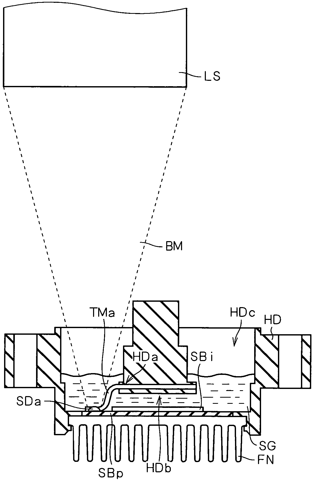
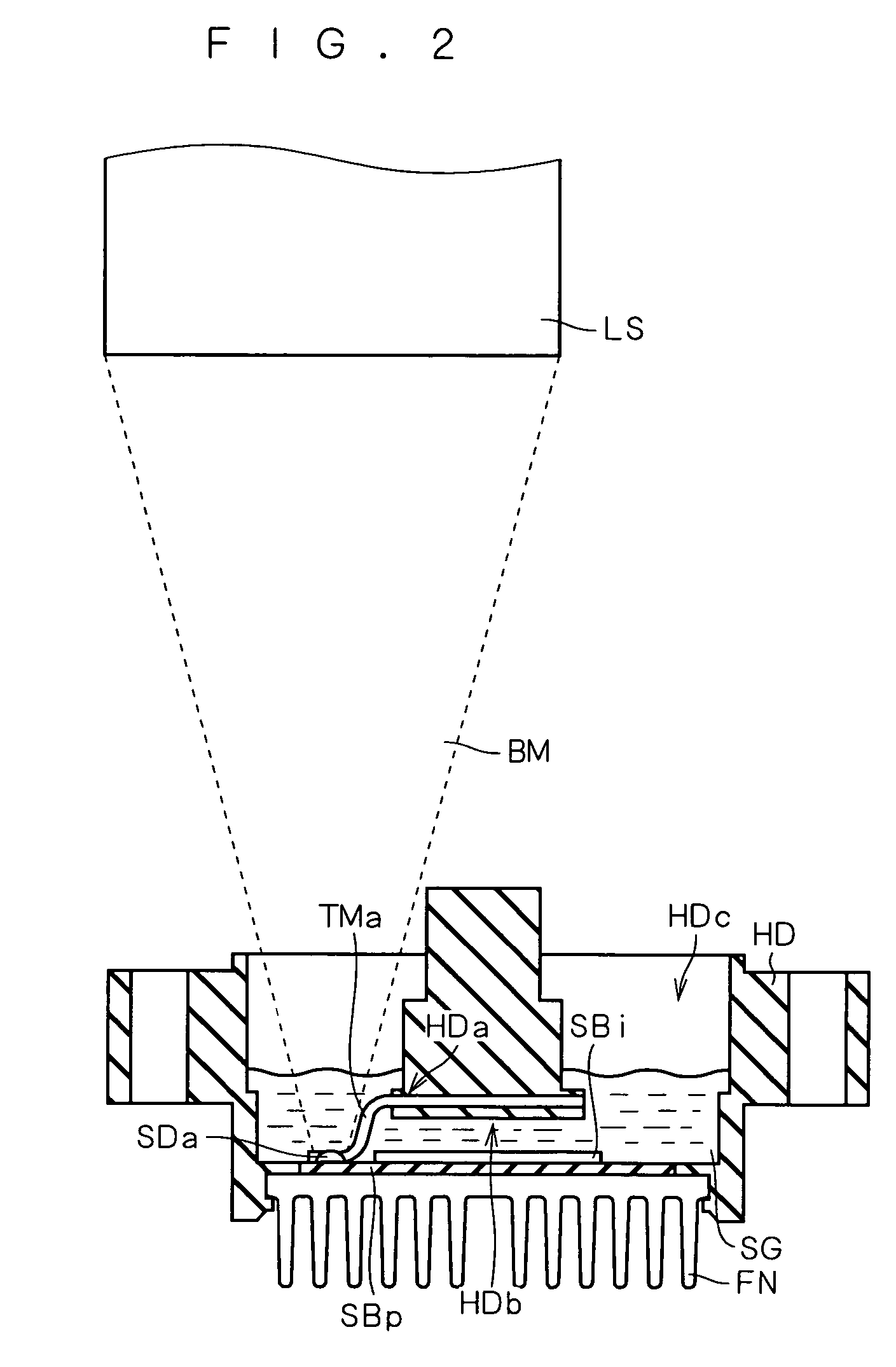
[0026]A preferred embodiment of the present invention provides a method of joining terminals by soldering, wherein solder joints of terminals are immersed in molten solder utilizing a springback phenomenon that occurs at flat portions of the terminals, and laser soldering is performed using a gas chamber that is made of a material which transmits a laser beam at least in part.

[0027]The utilization of the springback phenomenon eliminates the need to use a jig for pressing solder joints of terminals into molten solder and thus eliminates the need to provide an insertion port for such a jig within a gas chamber. Also, there is no need to provide an opening for the admission of a laser beam within a gas chamber. This results in the realization of a terminal joining method that reduces the occurrence of gas leakages and that allows control of increasing gas supply.

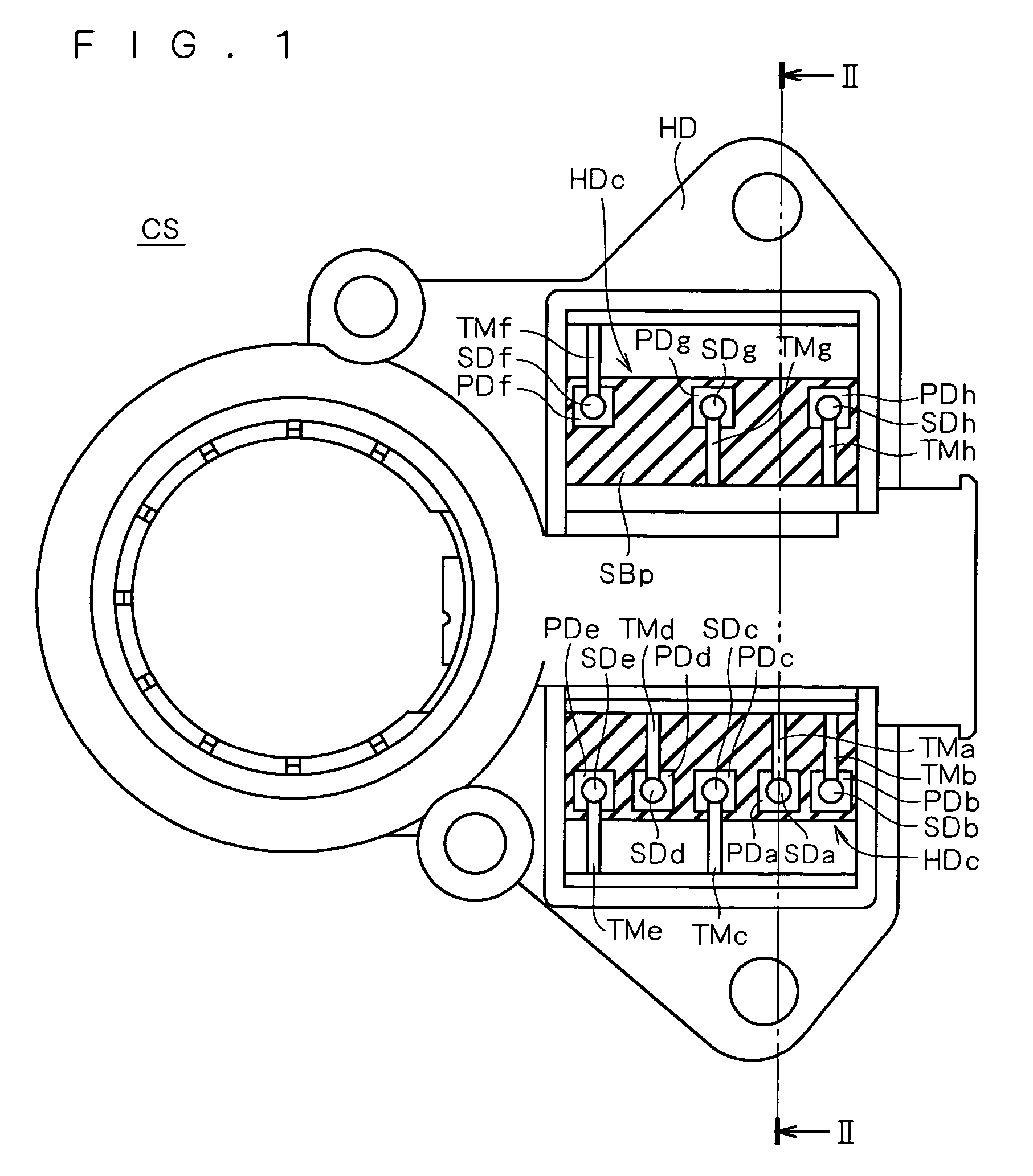
[0028]FIG. 1 is a top plan view showing the structure of a vehicle alternator component CS to which the terminal joining meth...


PUM

PropertyMeasurementUnit
optical axisaaaaaaaaaa
concentrationaaaaaaaaaa
diameteraaaaaaaaaa

Abstract

A method of joining terminals by soldering is provided which allows control of increasing gas supply even in soldering performed in a gas atmosphere within a gas chamber. Utilizing a springback phenomenon occurring at a flat portion of a terminal, a solder joint of the terminal is immersed in molten solder. Then, laser soldering is performed using a gas chamber made of a material which transmits a laser beam at least in part.

Description

BACKGROUND OF THE INVENTION[0001]1. Field of the Invention[0002]The present invention relates to a method of joining terminals to a printed circuit board by soldering.[0003]2. Description of the Background Art[0004]Various methods exist for joining terminals to a printed circuit board. For example, Japanese Patent No. 2768141 describes a technique using laser welding.[0005]Instead of laser welding as in the aforementioned Japanese Patent, soldering using laser heating can also be employed to join terminals to a printed circuit board.[0006]In soldering, a flux may be used for purposes such as prevention of oxidation and removal of oxides. Or, a silicone gel may be applied onto a printed circuit board after soldering for purposes such as assurance of insulation and shock absorption. There are also cases where a flux and a silicone gel are used in combination; for example, soldering using a flux is followed by the application of a silicone gel on a printed circuit board.[0007]In the co...

Claims


Application Information

Patent Timeline
Patent Type & Authority Patents(United States)
IPC IPC(8): B23K26/20B23K26/42H01R43/02B23K1/005H05K3/34
CPCB23K1/0056H01R43/0214H01R43/0221H01R43/0242H05K3/3421H05K3/3494H05K2203/0195H05K2203/0278H05K2203/107H05K2203/111Y02P70/50
Inventor OOHASHI, ATSUSHINISHITANI, SHOICHIROYAMADA, TAKAHIRO
Owner MITSUBISHI ELECTRIC CORP
Learn More