Device and method for recording video signal

Inactive Publication Date: 2007-09-04
ONKYO KK D B A ONKYO CORP
View PDF7 Cites 39 Cited by
  • Summary
  • Abstract
  • Description
  • Claims
  • Application Information

AI Technical Summary

Benefits of technology

[0007]This invention is accomplished under the above circumstance, and intends to provide a video signal recording device and method which can avoid an inconvenience in the display of the reproduced character information where the closed caption data immediately after the recording is started or the release of pause of the recording is done is discontinuous in the recording of the video signal with the character information of the closed caption superimposed thereon.
[0019]In this configuration, in a video tape recorder for recording e.g. an analog video signal, when the operation of recording the video signal or release of pause of the recording is started, on the basis of the control signal, the stored control code data is read out and recorded as the closed caption data together with the video signal. Thus, in the frames immediately after or before the recording is started and immediately after or before the pause of the recording is released, the inserted control code data indicative of “clear” as the closed caption data as well as the video signal is recorded. For this reason, the inconvenience in the reproduction display of the character information when the closed caption data has become discontinuous can be overcome.
[0023]In accordance with this configuration, an information recording device such as a DVD-RW for recording the digital video signal data encoded in e.g. an MPEG system, when the operation of recording the video signal or release of pause of the recording is started, a control signal for instructing insertion of the control code data is sent so that the control code data is inserted as the closed caption data. At this time, for example, the encoding unit for encoding the input video signal inserts the control code data when the input video signal is encoded by the encoding unit. Thus, in the frames immediately after or before the recording is started and immediately after or before the pause of the recording is released, the inserted control code data as the closed caption data as well as the video signal is recorded. For this reason, the inconvenience in the reproduction display of the character information when the closed caption data has become discontinuous can be overcome.
[0030]In the configuration described above, where the operation of recording of the video signal or release of the pause of the recording is started, the control code data for resetting the display of the closed caption data, e.g. control code data indicative of “clear” for canceling the displayed character information is inserted. Thus, in the frames immediately after or before the recording is started and immediately after or before the pause of the recording is released, the inserted control code data indicative of “clear” as the CC data as well as the video signal is recorded. For this reason, the inconvenience in the reproduction display of the character information when the closed caption data has become discontinuous can be overcome.
[0034]In accordance with this configuration, in an information recording device such as a DVD-RW for recording the digital video signal data encoded in e.g. an MPEG system, when the operation of recording the video signal or release of pause of the recording is started, a control signal for instructing insertion of the control code data is sent so that the control code data is inserted as the closed caption data. At this time, for example, the encoding unit for encoding the input video signal inserts the control code data when the input video signal is encoded by the encoding step. Thus, in the frames immediately after or before the recording is started and immediately after or before the pause of the recording is released, the inserted control code data as the closed caption data as well as the video signal is recorded. For this reason, the inconvenience in the reproduction display of the character information when the closed caption data has become discontinuous can be overcome.

Problems solved by technology

Therefore, immediately after recording is started or release of pause of the recording is performed, the CC data which has been input until immediately before is not recorded, but the continuity of the CC data is lost.
When the recorded tape subjected to the pause of recording / release thereof is played back and displayed on the television receiver designed for the closed caption, an inconvenience of disorder of the displayed character information occurred.

Method used


Image

  • Device and method for recording video signal
  • Device and method for recording video signal
  • Device and method for recording video signal

Examples


first embodiment

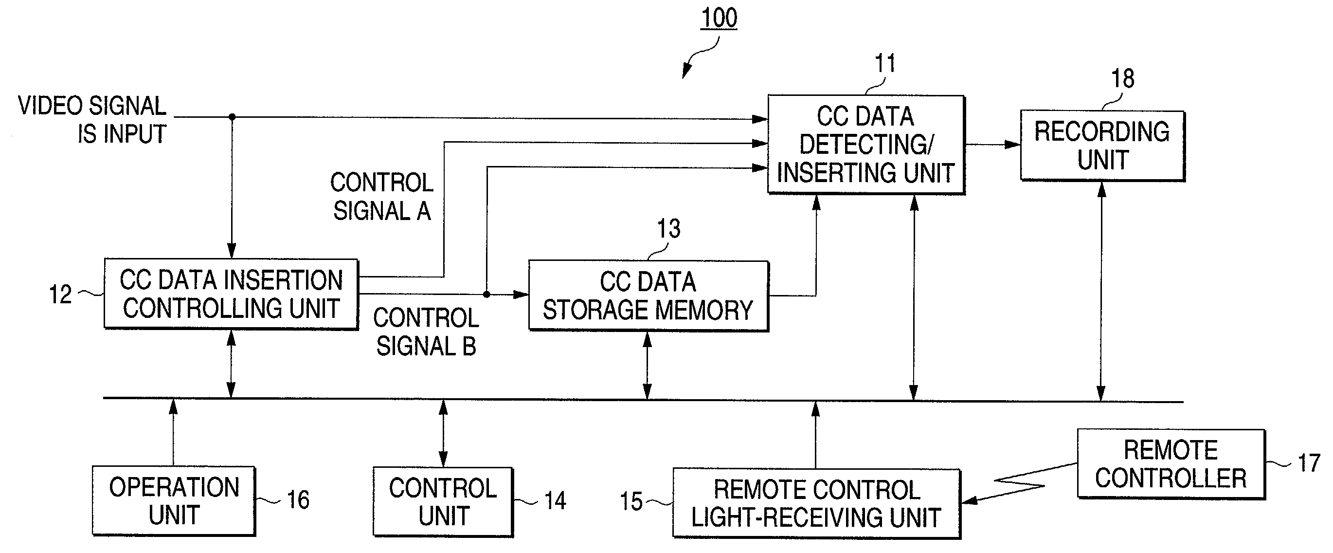
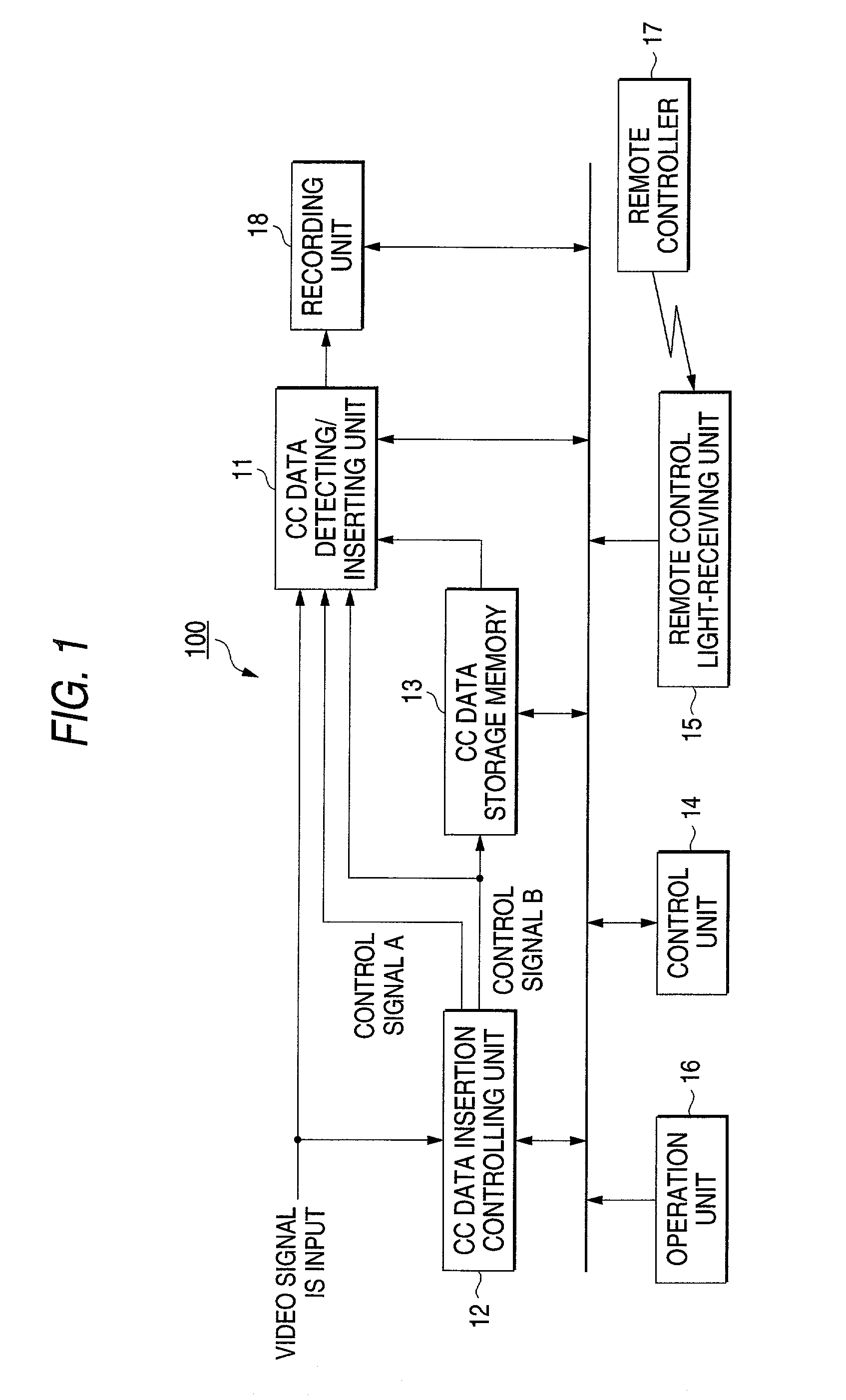
[0042]FIG. 1 is a block diagram of the main part of a video signal recording device 100 according to this invention. The video signal recording device constitutes a video tape recorder for recording a video signal on a video tape (not shown).

[0043]The video signal recording device 100 according to this embodiment includes a CC data detecting / inserting unit 11, a CC data insertion controlling unit 12 and CC data storage memory 13 which will be described later in detail. The video signal recording device further includes a control unit 14 which is constructed of a microcomputer (MPU) for controlling the entire device, a remote control light-receiving unit 15 for receiving a remote control signal from a remote controller 17, an operation unit 16 which is constructed of switches for inputting various operation commands, and a recording unit 18 for recording the video signal produced from the CC data detecting / inserting unit 11 on a video tape (not shown).

[0044]The CC data detecting / inse...

second embodiment

[0056]FIG. 5 is a block diagram of the configuration of the main part of a video signal recording device 200 according to this invention. This embodiment is directed to the case where an input video signal is encoded in the MPEG system, and the encoded digital video data is recorded on a disk optical recording medium such as DVD-RW.

[0057]The video signal recording device 200 includes an A / D converter 21 for converting an input analog video signal into a digital signal, a CC data detecting unit 22 for detecting the CC data superimposed on the video signal, a control unit 23 including a microcomputer (MPU) for controlling the entire device and others, an MPEG encoder 24 for encoding the digital data in a digital compressed video data in the MPEG system, a recording circuit 25 for creating a signal to be recorded on an optical recording medium 27 and a pick-up 26 for optically recording the video data on the optical recording medium 27 by emission of laser light.

[0058]The MPEG encoder ...


PUM


Abstract

A CC data detecting / inserting unit 11 detects the presence or absence of the CC data superimposed on an input video signal, and a control unit 14 decides the contents of the operation command by a remote control signal. Where the start of recording or release of pause of the recording is instructed, a CC data insertion controlling unit 12 produces a control signal so that a control code indicative of “clear” is read out from a CC data storage memory 13. The CC data detecting / inserting unit 11 inserts this control code data as the CC data. Thus, the CC data with the control code data indicative of “clear” inserted at a discontinuous point as well as the video signal is recorded. This overcomes the inconvenience of display of the information of coupled discontinuous characters.

Description

BACKGROUND OF THE INVENTION[0001]This invention relates to a video signal recording device and method for recording an input video signal with a closed caption character information superposed thereon.[0002]In the United States, in order that persons who have difficulty in hearing as well as persons with a normal healthy body can enjoy a television broadcasting, a closed caption system in which the character information representing audio contents superimposed on a video signal is displayed as a caption has been adopted in a broadcasting and video tape.[0003]In the closed caption system, character information of 16 bits (2 characters) is superimposed on e.g. a 21-th scanning line during a vertical blanking period of each field of the video signal. A television receiver or video tape recorder dealing with the closed caption is equipped with a decoder for the closed caption. The decoder extracts the information (closed caption data, hereinafter referred to as “CC data”) superimposed o...

Claims


Application Information

Patent Timeline
IPC IPC(8): H04N5/91H04N5/78G11B20/10H04N5/7826H04N5/85H04N5/92H04N7/025H04N7/03H04N7/035H04N9/804
CPCH04N5/9206H04N5/85H04N9/8042
Inventor KIMURA, TOMOHIROARIMA, KOICHI
Owner ONKYO KK D B A ONKYO CORP
Why Eureka
Try Eureka