Machine tool

a technology of machine tools and tools, applied in the field of machine tools, can solve problems such as lowering the machining accuracy

Inactive Publication Date: 2007-09-11
DMG MORI CO LTD
View PDF14 Cites 39 Cited by
  • Summary
  • Abstract
  • Description
  • Claims
  • Application Information

AI Technical Summary

Benefits of technology

[0007]The present invention was made in consideration of the above circumstances and it is an object thereof to provide a machine tool capable of realizing increased supporting stiff in a cutting direction of a tool post and as a result, capable of realizing enhanced machining accuracy.

Problems solved by technology

As a result, the aforesaid conventional machine has a problem of difficulty in ensuring supporting stiffness in the cutting direction of the lower tool post, which in some cases may possibly result in lowered machining accuracy.

Method used


Image

  • Machine tool
  • Machine tool
  • Machine tool

Examples


Embodiment Construction

[0040]An embodiment of the present invention will be hereinafter described based on the attached drawings.

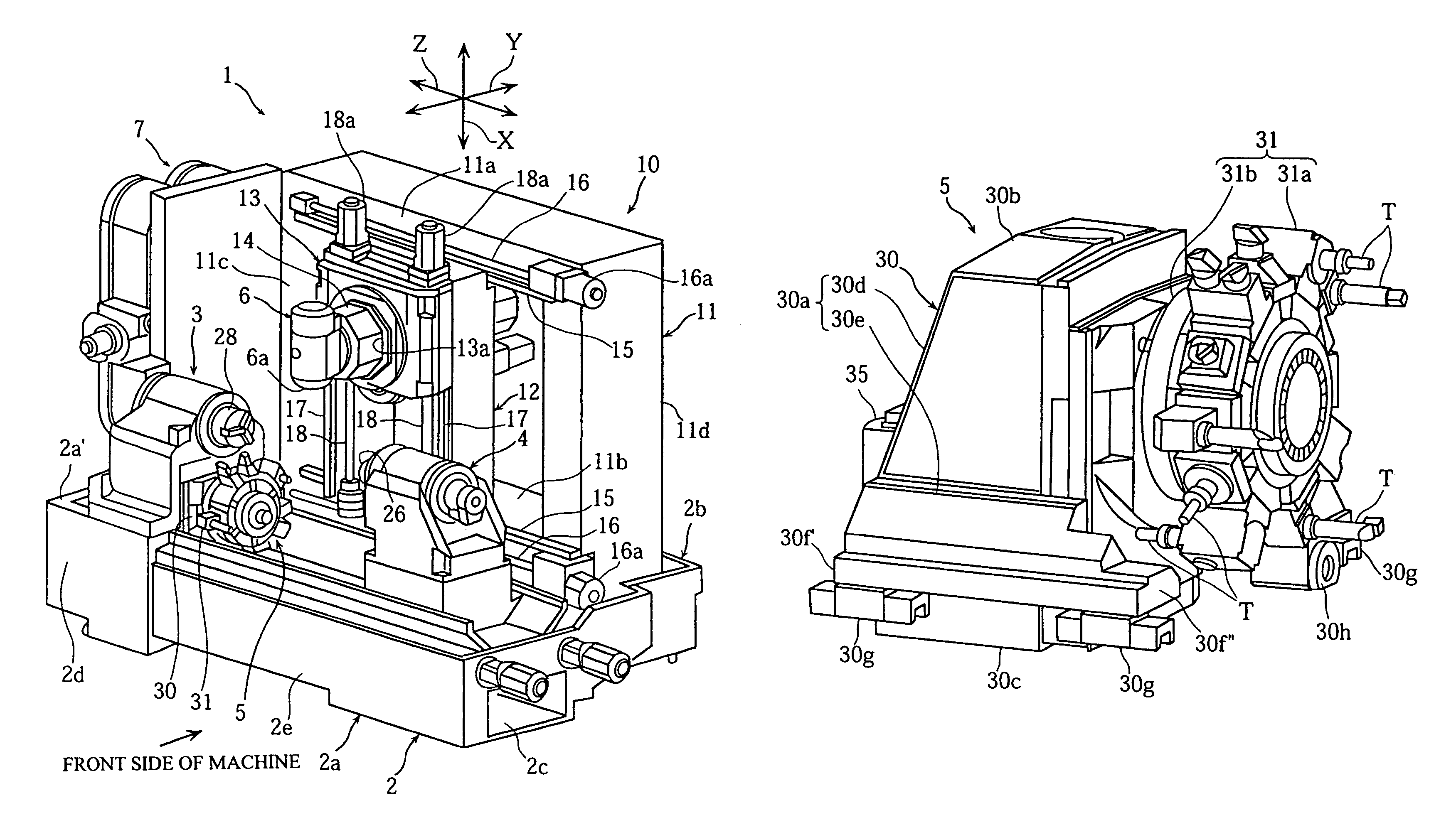
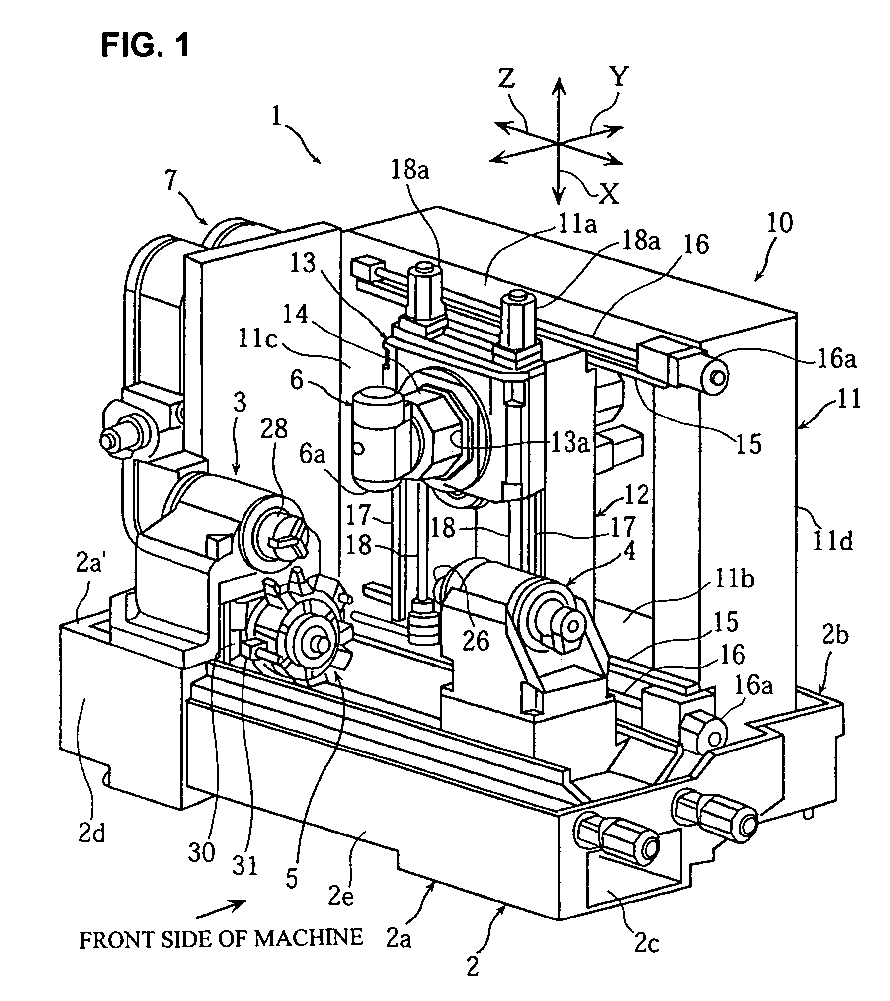
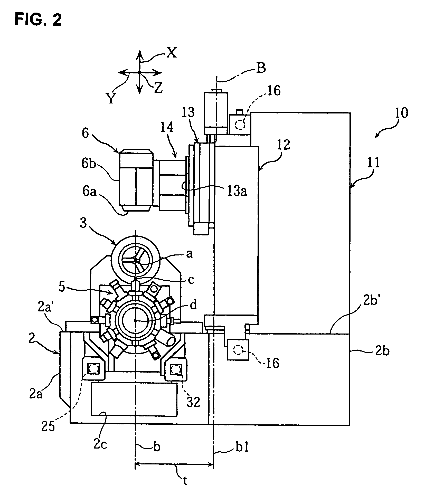
[0041]FIG. 1 to FIG. 18 are views to illustrate a composite lathe according to one embodiment of the present invention. FIG. 1 and FIG. 2 are a perspective view and a right side view of the composite lathe respectively, FIG. 3 and FIG. 4 are perspective views of a bed on which a first spindle headstock and a tool post are mounted, FIG. 5 is a front view of a supporting mechanism supporting a third spindle, FIG. 6 is a right side view of the first spindle headstock and the tool post, FIG. 7(a) to FIG. 7(c) are front views showing operations of the first spindle headstock, a second spindle headstock, and the tool post, FIG. 8 to FIGS. 11(a), (b) are views of the first spindle headstock, FIG. 12 is a perspective view of a cooling oil jacket of the first spindle headstock, FIG. 13 to FIG. 16 are views of the tool post, and FIG. 17 and FIG. 18 are views showing X-axis and Y-axis dire...


PUM

PropertyMeasurementUnit
cutting forceaaaaaaaaaa
stiffnessaaaaaaaaaa
reaction forceaaaaaaaaaa

Abstract

To provide a machine tool in which supporting stiffness of a tool post is increased, thereby enabling improvement in machining accuracy. When seen in a Z-axis direction, a tool post 5 includes: a supporting member 30 having a pair of left and right leg parts 30a, 30a and an upper beam part 30b coupling at least upper ends of the both leg parts 30a with each other; and a turret 31 to whose outer circumferential portion a plurality of tools are attached. The supporting member 30 is supported to be movable in a Z-axis direction between a first and a second spindle headstock 3, 4, and the turret 31 is supported to be movable in an X-axis direction by turret guide rails 33, 33 which are disposed on front faces of the left and right leg parts 30a, 30a.

Description

BACKGROUND OF THE INVENTION[0001]1. Field of the Invention[0002]The present invention relates to a machine tool including: a first spindle headstock disposed on a bed; a moving table disposed coaxially with the first spindle headstock; and a tool post disposed between the first spindle headstock and the moving table.[0003]2. Description of the Related Art[0004]An example of a machine tool of this type is structured such that a spindle headstock is fixedly disposed on a left end portion of a bed when seen from a front side of the machine and a lower tool post and an upper tool post are disposed on a lower side and an upper side of a tool post supporting part in a slanted shape respectively. The lower tool post is structured such that a lower saddle is supported to be movable in a spindle axis (Z-axis) direction by a Z-axis guide which is disposed on the tool post supporting part and a tool post main body is supported to be movable in a direction (X-axis direction) parallel to a suppo...

Claims


Application Information

Patent Timeline
Patent Type & Authority Patents(United States)
IPC IPC(8): B23P23/02B23B29/32B23B3/18
CPCB23B3/065B23B3/168B23Q1/01Y10T82/2508Y10T29/519Y10T29/5114Y10T82/2524B23Q2039/004
Inventor TAKEUCHI, SYUJITOKUMA, TSUTOMU
Owner DMG MORI CO LTD
Why Eureka
Try Eureka