Heat exchanger

a heat exchanger and axial direction technology, applied in indirect heat exchangers, heat exchange apparatus safety devices, lighting and heating equipment, etc., can solve the problems of difficult forming of cylindrical casings, difficult axial stretch, and inability to heat fluids, etc., to achieve uniform heat exchange and high durability.

Inactive Publication Date: 2007-09-11
T RAD CO LTD
View PDF18 Cites 15 Cited by
  • Summary
  • Abstract
  • Description
  • Claims
  • Application Information

AI Technical Summary

Benefits of technology

[0019]The heat exchanger of the present invention has the above constitution and the following advantages. That is, at least one first baffle plate 7 is fitted to the outer periphery at one end of the inner cylinder 6, with the outlet 11 and inlet 12 for the fluid to be heated and the heating fluid being positioned between the opposed ends of the inner cylinder 6 and the tube plates 5, the outer cylinder 10 being formed into a circular cylinder with the inner cylinder 6 being of a rectangular cross-section that encloses the outer periphery of the core 4. The presence of the first baffle plate 7 enables the fluid 2 to be heated or the heating fluid 1 to securely be delivered to the interior of the inner cylinder 6 to ensure a uniform heat exchange at respective parts. The fluid 2 to be heated or the heating fluid 1 can thus be prevented from flowing through the space defined between the inner tube 6 and the first baffle plate 7.
[0020]Since the outer cylinder 10 is formed into a circular cylinder whose outer periphery is provided with the corrugated portion 9 that is thermally expandable in the axial direction, its fabrication and expansion and contraction attendant on the thermal expansion become easy, achieving a high durability.

Problems solved by technology

Due to its square cross-section, however, the square-in-section of bellows-like thermal stress relaxation means tend to suffer from a drawback of being hard to smoothly stretch in its axial direction.
In addition, its fabrication is not easy.
Mere forming of a cylindrical casing would not allow a fluid to be heated to pass uniformly through parts of the core.

Method used


Image

  • Heat exchanger
  • Heat exchanger
  • Heat exchanger

Examples


Embodiment Construction

[0027]An embodiment of the present invention will now be described with reference to the drawings.

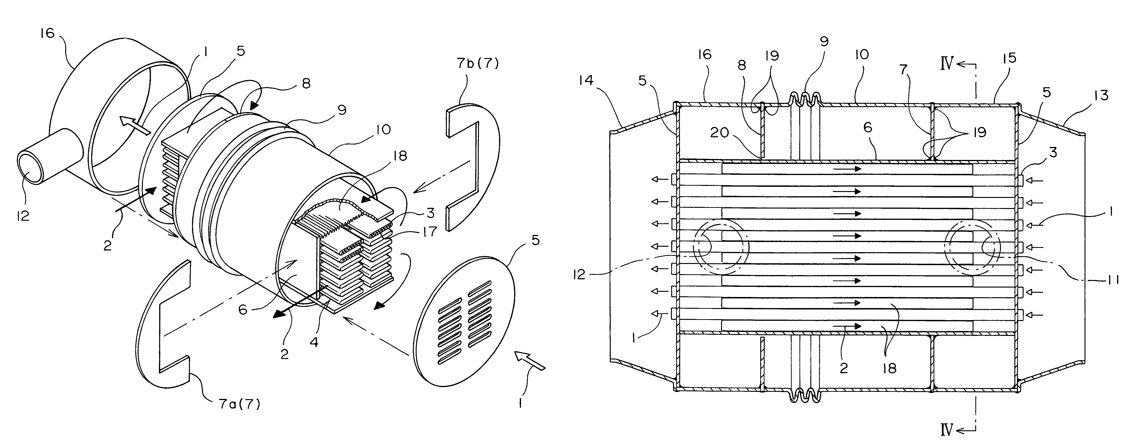
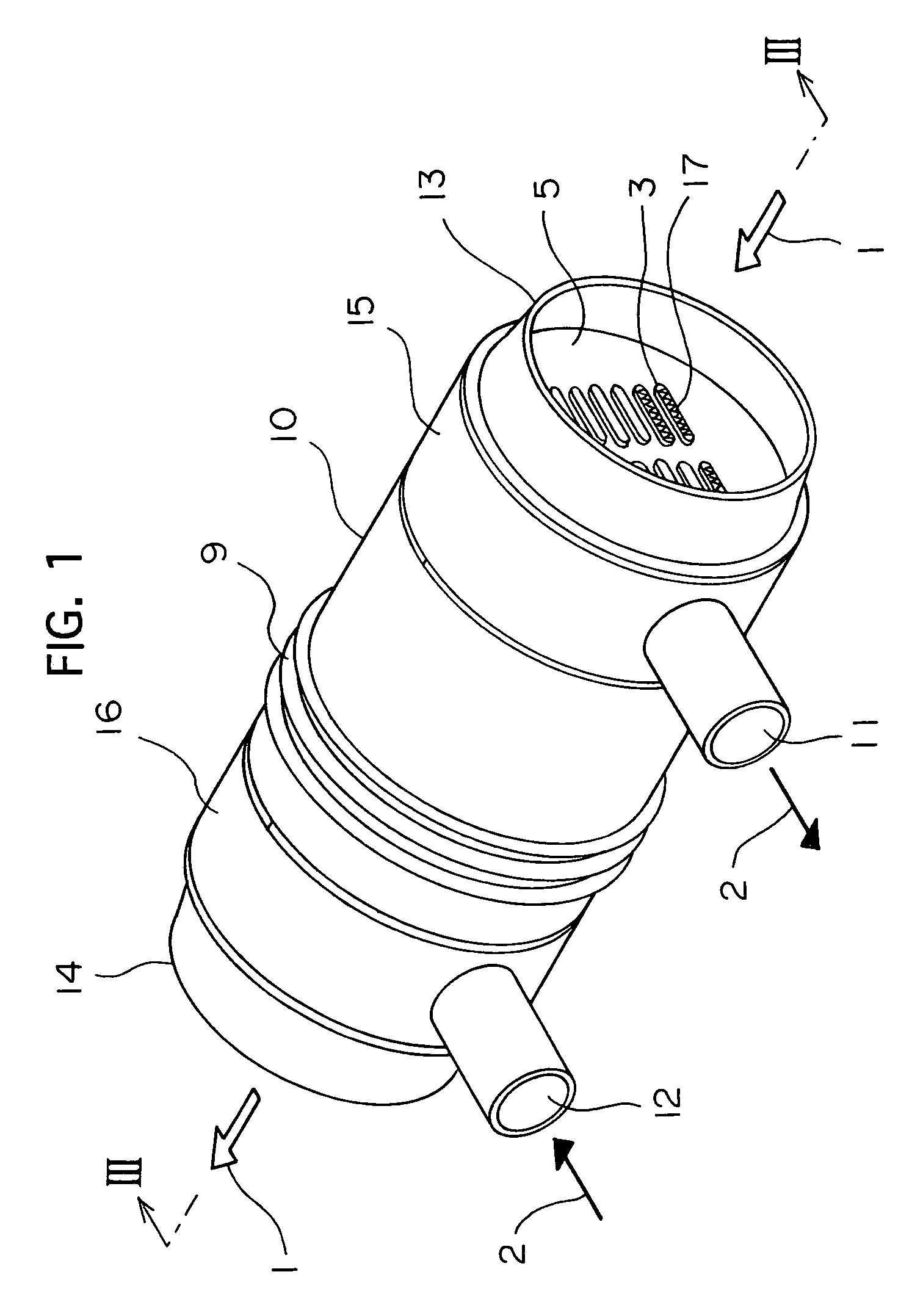
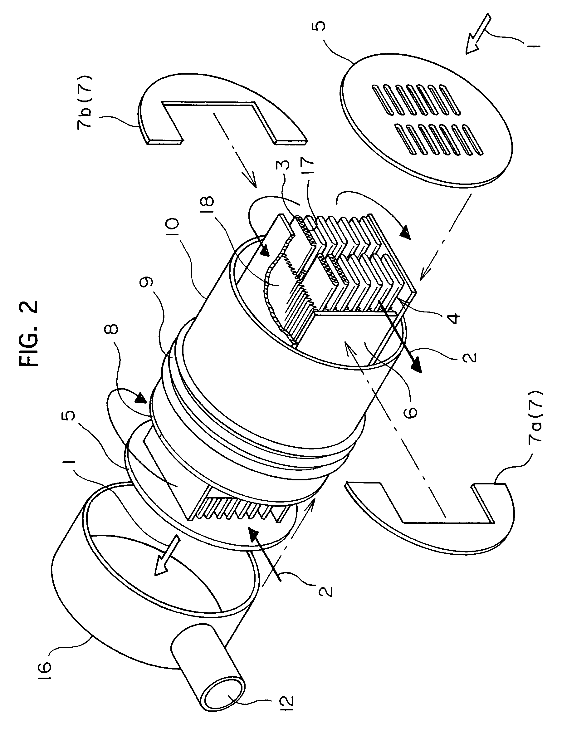
[0028]FIG. 1 is a perspective view of a heat exchanger of the present invention, FIG. 2 is an exploded explanatory view of the same, FIG. 3 is a longitudinal cross-sectional view of FIG. 1, and FIG. 4 is a cross-sectional view taken along line IV-IV of FIG. 3.

[0029]The heat exchanger includes a multiplicity of juxtaposed flat tubes 3 each having inner fins 17 in its interior, with outer fins 18 carrying a catalyst disposed between the adjacent flat tubes 3, to make up a core 4 in the aggregate. The flat tubes 3 are joined at their respective opposed ends to tube insertion apertures of a pair of discoidal tube plates 5 in an gas tight manner.

[0030]The outer periphery of the core 4 is covered with a square-in-section inner cylinder 6 except the vicinities of the pair of tube plate 5. The inner cylinder 6 includes two opposed side members having a length smaller than that of the flat tubes...


PUM

PropertyMeasurementUnit
temperatureaaaaaaaaaa
external heataaaaaaaaaa
thermal stressaaaaaaaaaa

Abstract

In order to provide a heat exchanger with casing having a multiplicity of tubes through the interiors of which a high-temperature gas for heating flows, wherein the thermal stress is smoothly accommodated and wherein a fluid to be heated or a heating fluid flows uniformly through the outsides of the tubes, a multiplicity of flat tubes are joined at their opposed ends to a pair of discoidal tube plates, the outer periphery of the flat tubes being enclosed by an inner cylinder having a rectangular cross-section except the opposed end portions of the flat tubes, with a pair of baffle plates being disposed at the opposed ends of the inner cylinder. The pair of baffle plates are covered with an circular outer cylinder having a corrugated portion that is thermally expandable, with an inlet and an outlet for the fluid to be heated or the heating fluid positioned between the pair of baffle plates and the tube plates.

Description

TECHNICAL FIELD[0001]The present invention relates to a heat exchanger for high temperature used in a fuel cell reformer, etc.BACKGROUND ART[0002]In a fuel cell using hydrogen and oxygen as its fuel, the hydrogen is generated by a reformer in the form of a high-temperature-use heat exchanger. The reformer acts to deliver hydrocarbon such as methanol and steam into a catalyst and applies thereto external heat to generate hydrogen.[0003]Examples of such a heat exchanger for the reformer include one disclosed in Japanese Patent Application Laid-Open Publication No. 2002-80203. This is arranged such that a multiplicity of juxtaposed flat tubes are joined at their respective opposed ends to square tube plates in an gas tight manner to form a core, with the tube plates in a pair being connected to each other by a square-in-section casing. The casing is provided at peripheries around one end and the other end thereof in the longitudinal direction, respectively, with an inlet for a reformin...

Claims


Application Information

Patent Timeline
Patent Type & Authority Patents(United States)
IPC IPC(8): F28D7/10F28F9/22F28F1/02C01B3/34F28D7/16F28F9/00H01M8/04
CPCC01B3/34F28D7/1661F28D7/1684F28F9/22C01B2203/0805F28D2021/0043F28F2265/26F28F9/00F28F9/02
Inventor SHINCHO, SHUKOICHIKAWA, SUSUMUSAITO, MASAKIAOYAMA, TADAMICHI
Owner T RAD CO LTD
Why Eureka
Try Eureka