Drainage system

a technology of draining system and draining pipe, which is applied in the direction of burettes/pipettes, laboratory glassware, instruments, etc., can solve the problems of complicated and expensive system, long treatment time, and troublesome operation of manual separation, and achieve the effect of simple mechanism

Inactive Publication Date: 2007-09-11
SHIMADZU CORP
View PDF35 Cites 23 Cited by
  • Summary
  • Abstract
  • Description
  • Claims
  • Application Information

AI Technical Summary

Benefits of technology

[0009]The object of the present invention is to provide a drainage system capable of ca...

Problems solved by technology

A conventional treatment such as manual separation requires troublesome operations, such as operation for bringing the magnet close to the vessel and operation for discharging supernatant liquid by a pipet...

Method used


Image

  • Drainage system
  • Drainage system
  • Drainage system

Examples


Embodiment Construction

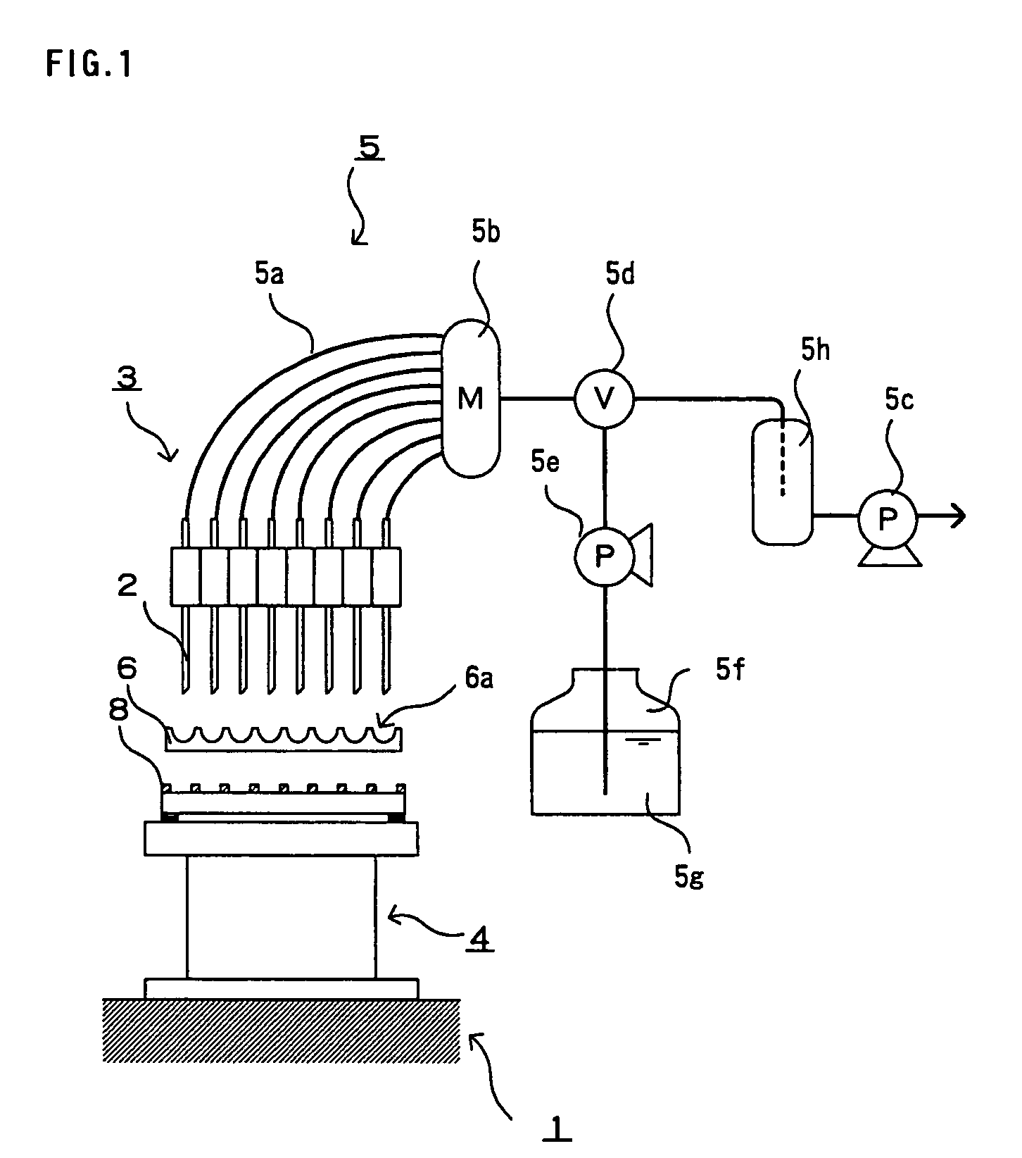
[0031]An outline of a drainage system according to the present invention will be described with reference to FIG. 1.

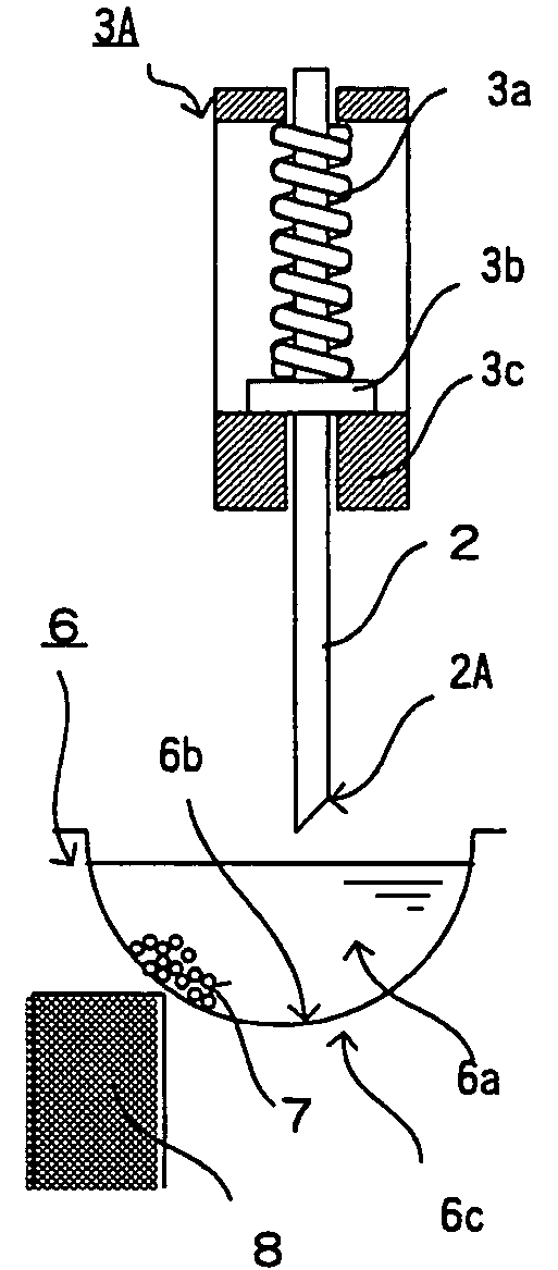
[0032]A drainage system 1 comprises a plurality of suction nozzles 2, suction nozzle moving means 3, magnetic particle holding means 4, and solution discharge means 5. The moving means 3 moves the suction nozzles 2 toward or away from a vessel 6 such as a micro-plate assembly. The holding means 4 holds magnetic particles in the vessel 6, thereby preventing the magnetic particles from being sucked out through the nozzles 2. The discharge means 5 causes the suction nozzles 2 to suck solution out of the vessel 6 and discharge solution into the vessel 6.

[0033]The vessel 6 is not limited to the micro-plate assembly, and may alternatively be any other vessel such as a vial that can hold a liquid sample. Magnetic particles for holding an objective substance is put in the vessel 6. In an embodiment of the present invention described below, the micro-plate assembly is used as t...


PUM


Abstract

In a system for sucking and discharging a solution from a vessel (micro-plate assembly 6) by suction nozzles 2, processes for suction, discharge, separation, etc. can be carried out with use of a simple mechanism, including suction nozzle moving means 3 for positioning the respective distal ends of the suction nozzles on the inner wall surface of the vessel, magnetic particle holding means 4 for magnetic particles 7 in a given position in the vessel, and solution discharge means 5 for sucking out and discharging the solution simultaneously from the vessel through the suction nozzles. Each or a combination of these means constitutes a drainage system.

Description

BACKGROUND OF THE INVENTION[0001]1. Field of the Invention[0002]The present invention relates to a drainage system for carrying out treatments that are required in predetermined processes for reagent addition, liquid suction, discharge, and separation, etc., using a vessel.[0003]2. Description of the Prior Art[0004]In the fields of clinical chemistry, biochemistry, pharmaceutical chemistry, etc. that involve chemical analyses, various treatments, such as reagent addition, liquid suction, discharge, and separation, etc., are carried out in reaction processes. In the case where a liquid sample in a vessel, such as a micro-plate assembly or vial, contains an objective substance, for example, magnetic particles that serve to hold the objective substance on their respective surfaces are loaded into the liquid sample. After the objective substance is held on the magnetic particles, supernatant liquid is sucked out and discharged, whereby the objective substance can be separated from the l...

Claims


Application Information

Patent Timeline
IPC IPC(8): B01L3/02G01N1/10B01J4/00G01N35/00G01N35/02G01N35/10
CPCG01N35/10G01N35/0098G01N35/028G01N35/1074
Inventor TAKII, TADAOKIINAMI, ATSUSHI
Owner SHIMADZU CORP
Why Eureka
Try Eureka