Alkylation process using UZM-8 zeolite

a technology of uzm-8 zeolite and alkylation process, which is applied in the direction of hydrocarbon preparation catalysts, physical/chemical process catalysts, bulk chemical production, etc., can solve the problem that the byproduct 1,1-diphenylethane (1,1-dpe) cannot be readily converted to ethylbenzene by alkylation or transalkylation

Inactive Publication Date: 2007-09-11
UOP LLC
View PDF5 Cites 30 Cited by
  • Summary
  • Abstract
  • Description
  • Claims
  • Application Information

AI Technical Summary

Benefits of technology

[0012]A process has been discovered to significantly reduce the formation of diphenylalkanes and / or alkyl aromatics with alkyl groups corresponding to dimerized or oligomerized feed olefin in an alkylation process to produce alkyl aromatics, such as ethylbenzene and cumene, by alkylation using solid catalysts containing UZM-8 zeolite. The process disclosed herein is particularly useful at a low molar ratio of aryl groups per C2-C4 alkyl group, such as 6 or less. The process passes a feed aromatic, a C2-C4 olefin, and an alkylated derivative of the feed aromatic to an alkylation catalyst bed containing UZM-8 zeolite. The concentration of the C2-C4 olefin based on the weight of the feed aromatic, the C2-C4 olefin, and the alkylated derivative of the feed aromatic passed to the UZM-8 zeolite bed can be relatively high, such as at most 17 wt-%, at most 10 wt-%, or at most 5 wt-%. The concentration of the C2-C4 olefin may preferably be positive and near zero in circumstances, but minimum concentrations of 0.1 wt-% or 1.5 wt-% may also be used. The alkylated derivative of the feed aromatic may have from one to six more C2-C4 alkyl groups than the feed aromatic, and preferably the alkylated derivative is a dialkylated or trialkylated derivative of the feed aromatic. The alkylated derivative may be introduced to the UZM-8 zeolite bed in any process stream, and preferably the stream is an aliquot recycled portion of the UZM-8 zeolite bed effluent. A relatively low amount of the aliquot portion of the effluent may be used, such as a ratio of the weight of the aliquot portion to the combined weight of the feed aromatic and the C2-C4 olefin of at least 0.1. Higher ratios of at least 1.0, 2.5, or 4.0 can also be used. This result using a solid catalyst comprising UZM-8 zeolite was surprising. UZM-8 zeolite has a unique layered structure, and its performance was not predictable from the prior art zeolites such as beta, omega, ZSM-5, PSH-3, MCM-22, MCM-36, MCM-49, and MCM-56.
[0013]An alkylation process of alkylating benzene with ethylene, propylene, or butene using effluent recycle shows a significant selectivity advantage if UZM-8 zeolite is used instead of a zeolite used in prior art processes. By using the process disclosed herein, ethylbenzene and cumene processes can now minimize formation of 1,1-DPE and / or other undesired byproducts even while operating profitably at low molar ratios of aryl groups per ethyl group.
[0014]Without limiting the process disclosed herein to any particular theory, a working hypothesis may in part explain the observed results. It is believed the unique layered structure of UZM-8 zeolite makes available a relatively large number of catalytically active sites near or on the surface of the UZM-8 zeolite. Once monoalkylation at an active site, the resulting monalkylated aromatic can be readily removed from the surface. This reduces the formation of polyalkylated and heavier byproducts. Using effluent recycle with UZM-8 zeolite facilitates the transport of the monoalkylated aromatic from the active site. This working hypothesis explains the decreased formation of diarylalkanes and other byproducts when alkylating aromatics with ethylene, propylene, butenes, and higher olefins. For example, with ethylene alkylating benzene less 1,1-DPE and butylbenzenes would form. Where the olefin is propylene for instance, less 2,2-diphenylpropane (2,2-DPP) and hexylbenzenes would form, and possibly less 1,1-diphenylpropane (1,1-DPP) too. In the case where the olefin is butene, less diphenylbutanes and butylbenzenes would form.

Problems solved by technology
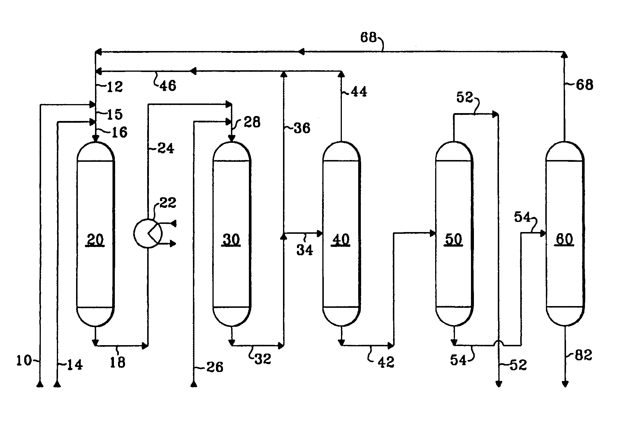
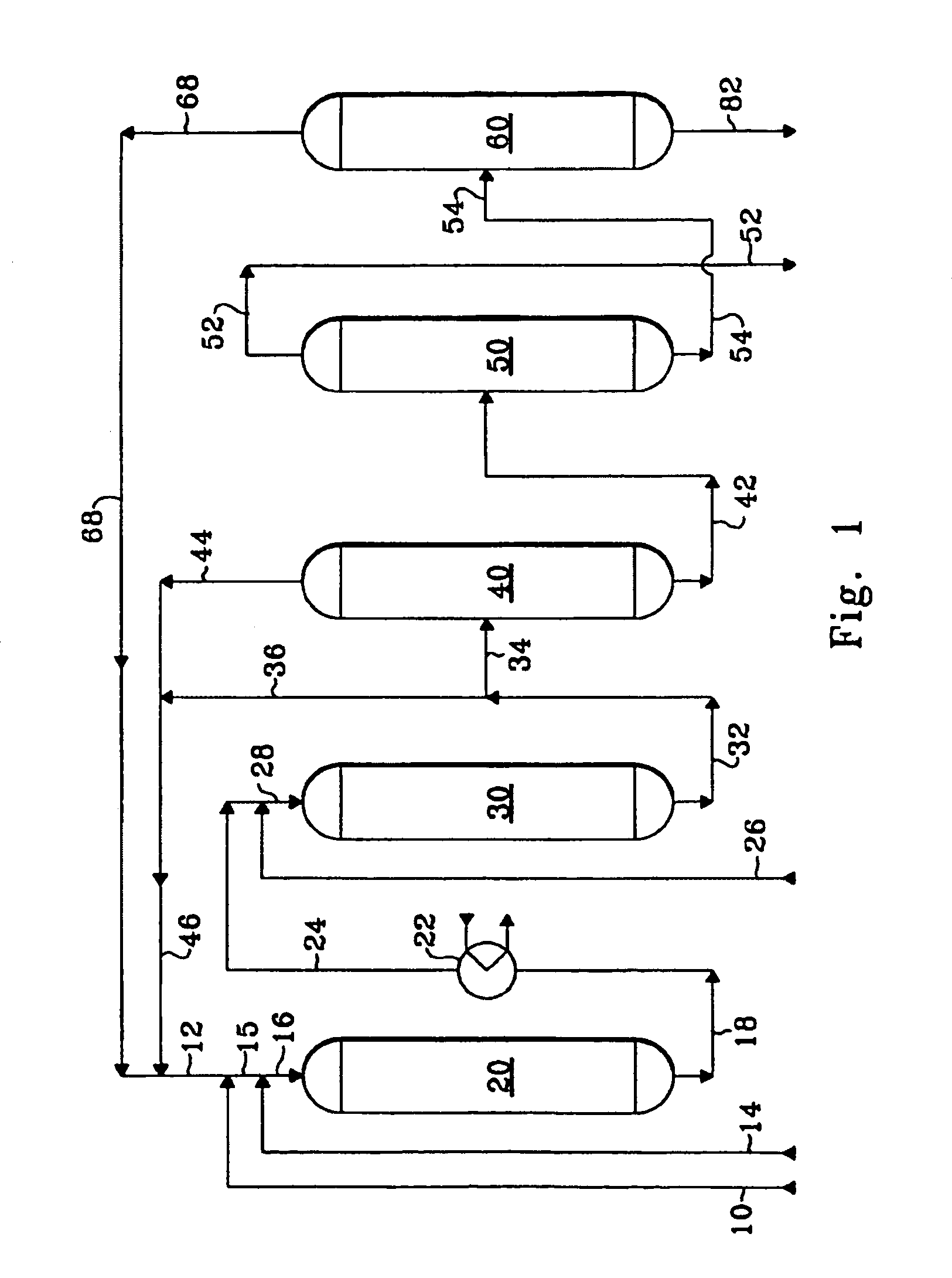
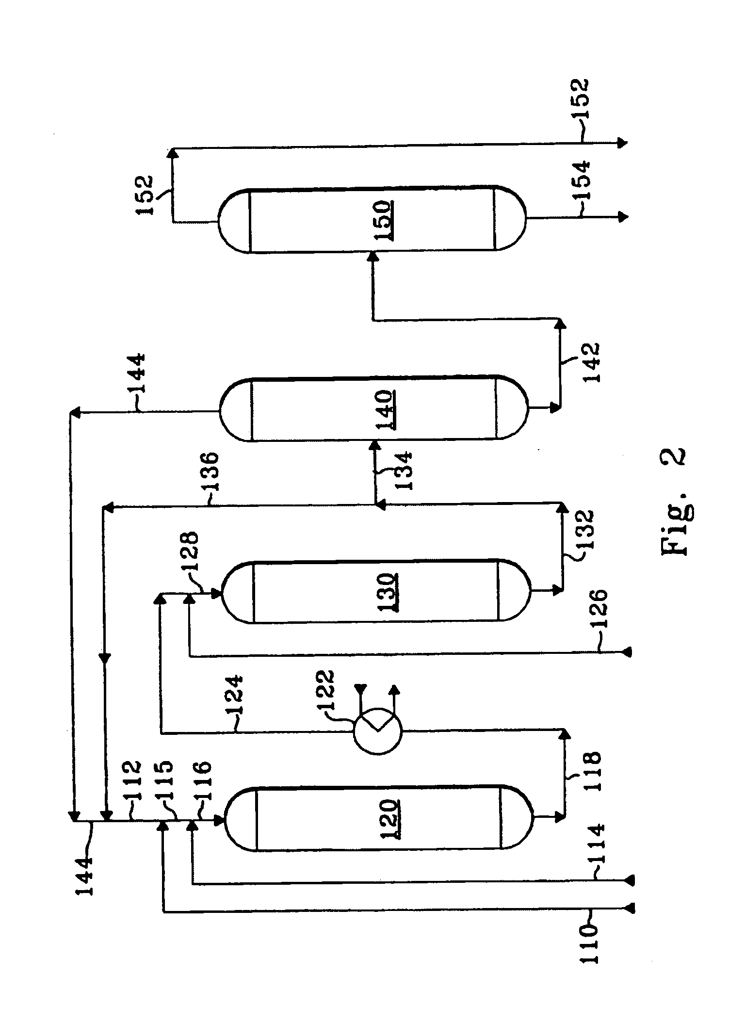
One disadvantage of alkylation-transalkylation processes, regardless of whether the alkylation and transalkylation reactions occur in the same or separate reaction zones, is that byproduct 1,1-diphenylethane (1,1-DPE) can not be readily converted to ethylbenzene by alkylation or transalkylation.

Method used


Image

  • Alkylation process using UZM-8 zeolite
  • Alkylation process using UZM-8 zeolite
  • Alkylation process using UZM-8 zeolite

Examples


example 1

[0088]A fresh alkylation catalyst comprising 70 wt-% zeolite beta and 30 wt-% alumina binder was prepared and is designated as Catalyst A. The zeolite beta for Catalyst A was prepared in substantially the same manner as described in U.S. Pat. No. 5,522,984.

[0089]An aluminosilicate reaction mixture was prepared in the following manner. A 7329.73 g portion of DEDMAOH (20% aq) was added to a tank. A 804.38 g portion of Al (Osec-Bu)3 (95%+) was added to the tank, and the resulting solution was thoroughly mixed for 45 min. A 2000 g quantity of deionized water was then added to the solution, followed by the addition of a 2526.96 g portion of precipitated silica (Ultrasil™ VN SP3, 89% SiO2). Next, a solution of 126.69 g of NaOH dissolved in 212.25 g of deionized water was prepared and added to the reaction mixture and the reaction mixture was thoroughly mixed for 30 min. The reaction mixture was then transferred to a 19-L stirred reactor. The tank was rinsed with 1000 g of deionized water ...

example 2

[0095]The experimental procedure used in the tests for Example 1 was as follows. A volume of the catalyst to be tested was loaded into a cylindrical reactor. The reactor was equipped with a thermocouple in a thermowell located to measure temperatures at distances along the length of the fixed catalyst bed. Dry benzene was passed through the reactor at 260° C. (500° F.) and at a benzene LHSV of 6.7 hr−1 for 24 hours.

[0096]Subsequently, the flow of fresh benzene was adjusted and the reactor inlet temperature was lowered to a temperature about 50° C. (90° F.) below the desired distance average bed temperature (DABT) for the initial testing conditions. As used herein, DABT means the temperature calculated by plotting the catalyst bed temperature versus distance along the catalyst bed, computing the area under the curve from the inlet to the outlet of the catalyst bed, and dividing the area by the length of the catalyst bed. Fresh ethylene was introduced into the reactor. Then a portion ...

example 3

[0101]The experimental procedure used in the tests for Example 3 was the same as for Example 2, except that for the tests for Example 3 the catalyst was Catalyst D, the ethylene WHSV was about 0.89 hr−1, and the molar ratio of fresh benzene to fresh ethylene was about 1.8. In Example 3, the R / FF was about 4.3 during tests 1 and 2. Subsequently, the reactor effluent recycle was stopped during test 3. It is believed that minimal catalyst deactivation occurred over the duration that the tests were performed.

[0102]The results shown in Table 2 are averages from measurements and / or analyses at each test condition. Table 2 shows that at nearly the same ethylene conversion recycling reactor effluent increased the EB selectivity and the total selectivity to (EB+DEB+TEB+TeEB), and decreased the total selectivities to (C4-Bz+C4-EB+C4-DEB ) and (DPE+EDPE). In addition, recycling reactor effluent decreased by at least 66% the selectivities to non-aromatics and to compounds heavier than DPE and E...


PUM

PropertyMeasurementUnit
mole ratioaaaaaaaaaa

Abstract

A process for the alkylation of aromatics with olefins using a solid catalyst bed containing UZM-8 zeolite is disclosed. A polyalkylated aromatic is passed to the catalyst bed to reduce the concentration of the olefin at alkylation conditions. A portion of the effluent recovered from the catalyst bed may be recycled to the catalyst bed. Such operation can decrease the catalyst deactivation rate and the formation of diphenylalkanes. The process disclosed herein is applicable to processes for the production of a wide variety of commercially important alkylated aromatics, including ethylbenzene and cumene.

Description

CROSS-REFERENCE TO RELATED APPLICATION[0001]This application is a Continuation-In-Part of application Ser. No. 10 / 828,989, filed Apr. 21, 2004 and now U.S. Pat. No. 7,091,390, the contents of which are hereby incorporated by reference in its entirety, which is a Continuation-in-Part of application Ser. No. 10 / 395,466, filed Mar. 21, 2003 and now U.S. Pat. No. 6,756,030, the contents of which are hereby incorporated by reference in its entirety, and of application Ser. No. 10 / 395,624, filed Mar. 21, 2003 (now abandoned), the contents of which are hereby incorporated by reference in its entirety.FIELD OF THE INVENTION[0002]This invention relates to a process for producing monoalkylated aromatic compounds by alkylation. Specifically, this invention relates to highly-selective alkylation and transalkylation to produce cumene and ethylbenzene.BACKGROUND OF THE INVENTION[0003]Alkylation of aromatic compounds with a C2 to C4 olefin and transalkylation of polyalkylaromatic compounds are two...

Claims


Application Information

Patent Timeline
Patent Type & Authority Patents(United States)
IPC IPC(8): C07C2/66
CPCB01J29/06B01J29/70C07C2/66C07C6/126C07C15/073C07C15/085B01J29/7007B01J2229/42C07C2521/04C07C2529/70Y02P20/584Y02P20/52C07C2/64C07C2/12C07C2/10C07C2/00
Inventor JAN, DENG-YANGJOHNSON, JAMES A.SCHMIDT, ROBERT J.WOODLE, GUY B.
Owner UOP LLC
Why Eureka
Try Eureka