Electric power steering apparatus

a technology of electric power steering and electric motor, which is applied in the direction of magnetic circuits characterised by magnetic materials, dynamo-electric components, and magnetic circuit shapes/forms/construction, etc. it can solve the problems of unintended force, torque loss, and loss of electric motor output torque, so as to improve the resistance to vibration and noise, vibration and noise

Inactive Publication Date: 2007-09-11
NSK LTD
View PDF20 Cites 16 Cited by
  • Summary
  • Abstract
  • Description
  • Claims
  • Application Information

AI Technical Summary

Benefits of technology

[0012]However, as for conventional column-type electric power steering apparatuses, there is demand for further enhancement of the resistance to vibration and noise caused by torque loss fluctuation. Since, with a column-type electric power steering apparatus, an electric motor is located at a position close to the driver, vibration and noise caused by the electric motor's torque loss fluctuation are easily transmitted to the driver (or passengers). So, sufficient quietness has not yet been achieved.
[0013]Accordingly, the present invention has been made considering the above-described problem peculiar to an electric power steering apparatus, i.e., cogging of a brushless motor that causes discomfort in a driver from the vibration and noise. In particular, it is an object of the present invention to provide an electric power steering apparatus that can achieve a high level of quietness by employing, as a stator's mechanical structure, a structure that can improve anti-vibration and anti-noise properties, and thereby suppress the occurrence of cogging due to torque loss fluctuation of an electric motor and reduce or suppress transmission of vibration and noise due to the cogging torque.
[0017]The present invention employs a resin-filled portion formed by filling the slots with a resin material after winding the coil around the plurality of stator teeth, and / or a partially press-fitted configuration between the back core and the yoke. Consequently, the resin-filled portion functions as a means for improving stator's rigidity, blocking vibration, and the like, while the partially press-fitted configuration functions to prevent the deterioration of the magnetic property of the stator material and to reduce the number of transmission paths for vibration and noise. Accordingly, it is possible to provide an electric power steering apparatus that can achieve a high level of quietness by employing, as a stator's mechanical structure, a structure that can improve anti-vibration and anti-noise properties, and thereby suppress the occurrence of cogging due to torque loss fluctuation of the electric motor and reduce or suppress transmission of vibration and noise due to such cogging torque.

Problems solved by technology

Torque loss means loss of an electric motor's output torque caused by friction arising from the motor structure, and other electromagnetic factors.
Torque loss adds unintended force or opposite-direction force to steering direction even in the case of slight steering during straight-ahead driving, and degrades the steering sensation.
Particularly when torque loss fluctuation is large, the fluctuation turns into physical vibration, which is then transmitted to the steering wheel, causing cogging.
Such cogging brings a bad or uncomfortable feeling to a driver, and thus it is necessary that an electric motor used for an electric power steering apparatus generates small torque loss fluctuation.
Since, with a column-type electric power steering apparatus, an electric motor is located at a position close to the driver, vibration and noise caused by the electric motor's torque loss fluctuation are easily transmitted to the driver (or passengers).
So, sufficient quietness has not yet been achieved.

Method used


Image

  • Electric power steering apparatus
  • Electric power steering apparatus
  • Electric power steering apparatus

Examples


Embodiment Construction

[0024]With reference to FIGS. 1 through 6, an electric power steering apparatus according to one embodiment of this invention is explained below.

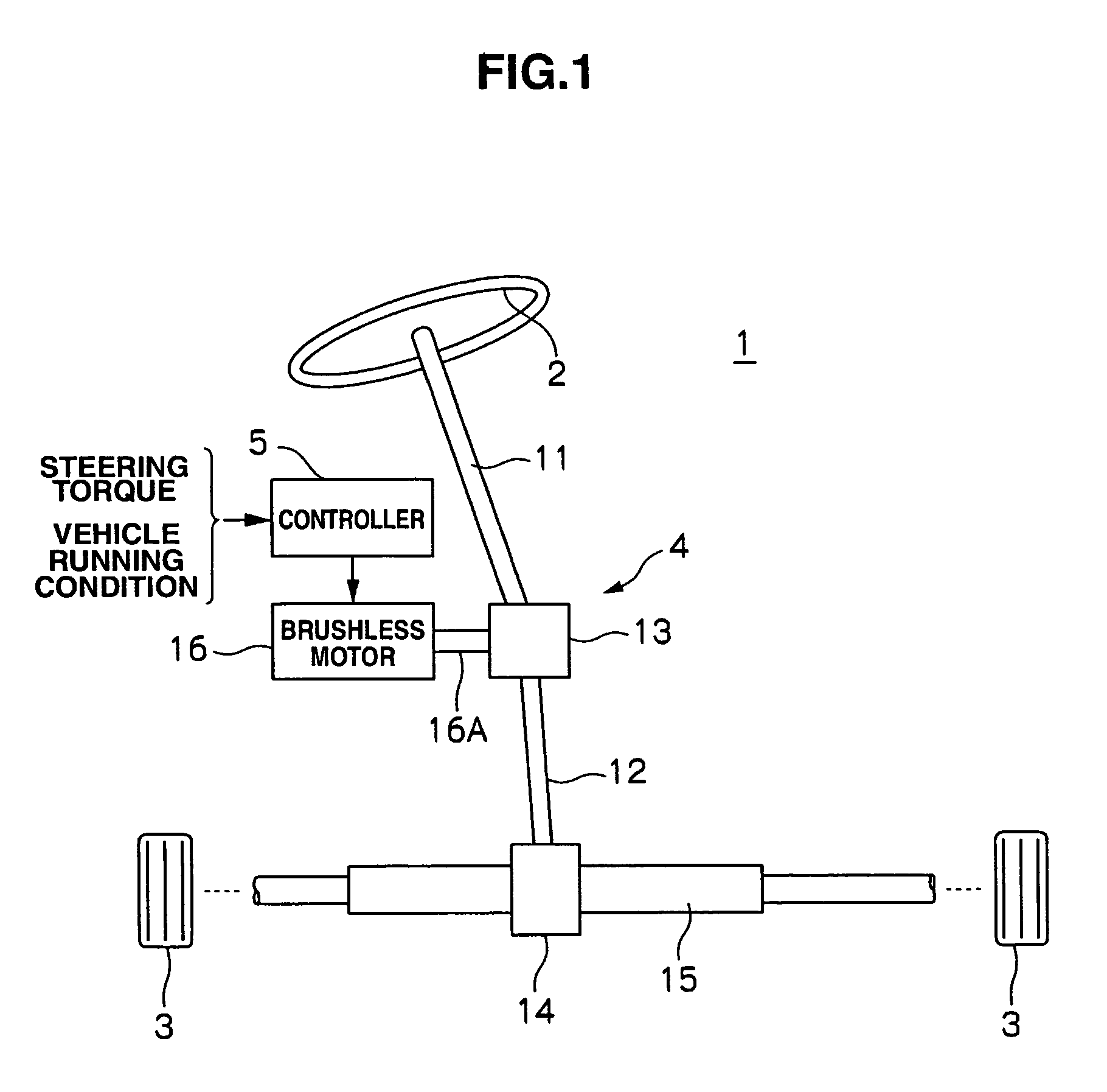
[0025]As shown in FIG. 1, this electric power steering apparatus has a steering mechanism 4 interposed between a steering wheel 2 and wheels 3, and a controller 5 for controlling the generation of a steering force by the steering mechanism 4.

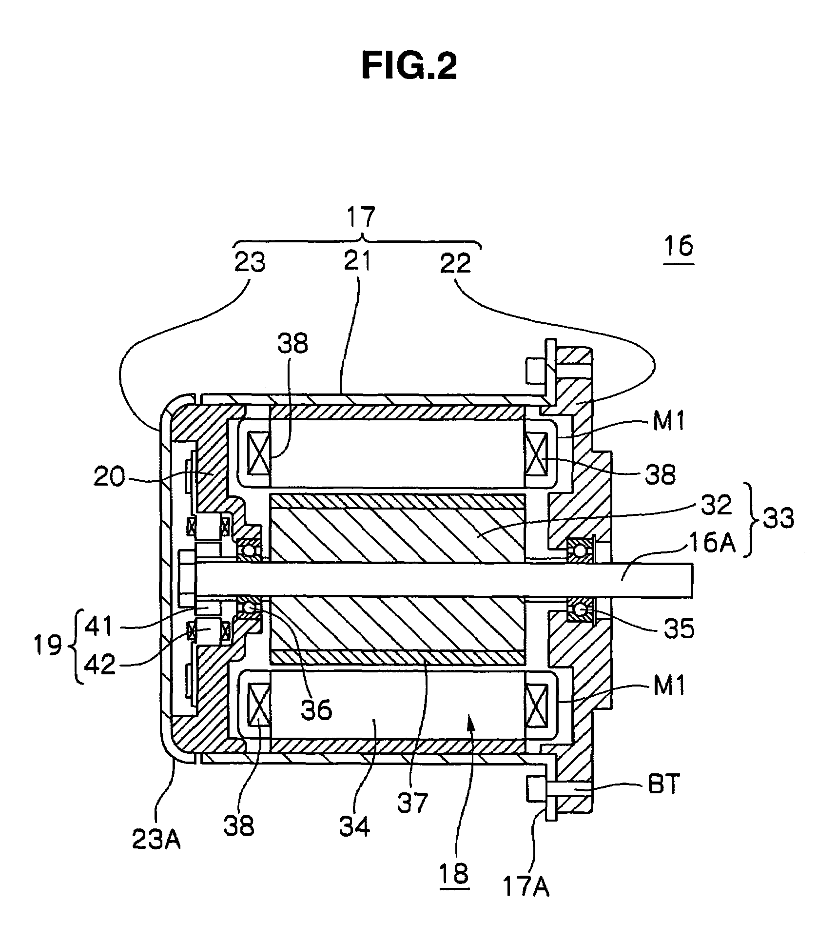
[0026]The steering mechanism 4 has: a column shaft 11 joined to the steering wheel 2; an intermediate shaft 12; a worm gear 13 interposed between the column shaft 11 and the intermediate shaft 12; and a gear 14 and a rack 15 joined between the intermediate shaft 12 and the wheels 3. Furthermore, the worm gear 13 engages with an output shaft 16A of a brushless motor 16 that is an electric motor. The brushless motor 16 is activated to rotate in response to a signal (activating current) by the controller 5, and gives a steering-assist force to the steering mechanism 4.

[0027]The steering force applied to th...


PUM

PropertyMeasurementUnit
steering torqueaaaaaaaaaa
distanceaaaaaaaaaa
cylindrical shapeaaaaaaaaaa

Abstract

The electric power steering apparatus includes a brushless motor as an electric motor. The motor has a rotor and a stator 34. The stator 34 includes: a back core BY; a plurality of teeth TS disposed along the circumference of the back core protruding from the back core BY toward its radial center and forming slots SL therebetween; and an exciting coil 38 wound around each of the teeth TS. Each of the slots SL is filled with a resin material. The back core BY is partially press-fitted into a yoke 21 so that the outer surface of the back core BY comes partially into contact with the inner surface of the yoke 21 along their circumferences.

Description

CROSS-REFERENCE TO RELATED APPLICATION[0001]This application relates to and claims priority from Japanese Patent Application No. 2004-206191, filed on Jul. 13, 2004, the entire disclosure of which is incorporated herein by reference.BACKGROUND[0002]1. Field of the Invention[0003]The present invention relates to an electric power steering (EPS) apparatus for vehicles that uses an electric motor to assist the manual steering force applied by a driver. More particularly, this invention relates to an electric power steering apparatus with a function reducing vibration and noise.[0004]2. Description of Related Art[0005]Lately, almost all vehicles are equipped with a power steering apparatus that assists the steering force applied by a driver.[0006]As one example of such a power steering apparatus, an electric power steering (EPS) apparatus is known. The known electric power steering apparatus includes, for example, a torque sensor for detecting steering torque applied to wheels, and an e...

Claims


Application Information

Patent Timeline
Patent Type & Authority Patents(United States)
IPC IPC(8): H02K1/04H02K1/06H02K15/00
CPCH02K1/185Y10T29/49009H02K5/08
Inventor BABA, TAKASHIOKAMURA, MANABUNAKAYAMA, SACHIO
Owner NSK LTD
Why Eureka
Try Eureka