Display device and electronic equipment having the same comprising a region for reflecting a polarized light and a region for absorbing the polarized light

a display device and electronic equipment technology, applied in static indicating devices, instruments, non-linear optics, etc., can solve the problems of deteriorating display quality, affecting and the conventional display device cannot avoid deterioration of display quality, etc., to achieve rapid deterioration of display characteristics such as color tone and contrast, and enhance the brightness of the reflective display device.

Active Publication Date: 2007-09-11
BOE TECH GRP CO LTD
View PDF36 Cites 145 Cited by
  • Summary
  • Abstract
  • Description
  • Claims
  • Application Information

AI Technical Summary

Benefits of technology

[0009]Since the display unit and the display switching unit are optically adhered to each other, it is possible to restrain deterioration of the visibility (for example, contrast) for the display condition of the display unit, due to the boundary reflection of the display unit and the display switching unit. Since the display unit and the display switching unit are optically adhered to each other, one is supported by the other in the display unit and the display switching unit, thereby enhancing the rigidity or strength. Therefore, it is possible to obtain the flatness of the display screen and improve the robustness of the device. Especially, the visibility of the display condition of the display unit can be enhanced by making the display switching unit thin. Even if the rigidity of the display switching unit is deteriorated by making it thin, the flatness and the robustness can be obtained by supporting the display switching unit with the display unit.
[0037]In the invention, it is preferable that the second polarization component selecting means is absorptive polarization selecting means for transmitting the one of the polarization components and absorbing the other polarization component. According to this, the surface reflection of the second polarization component means in the display mode can be reduced, thereby further enhancing the quality of the display image in the display mode.

Problems solved by technology

Therefore, there are problems such that contrast is deteriorated due to a boundary reflection in both sides of the display switching unit, coloring caused by the optical characteristic of the display switching unit, the characteristic of the viewing angle is deteriorated, and blurring of a display image easily occurs.
In any case, the conventional display device cannot avoid deterioration of the display quality caused by the double structure of the display unit and the display switching unit.

Method used


Image

  • Display device and electronic equipment having the same comprising a region for reflecting a polarized light and a region for absorbing the polarized light
  • Display device and electronic equipment having the same comprising a region for reflecting a polarized light and a region for absorbing the polarized light
  • Display device and electronic equipment having the same comprising a region for reflecting a polarized light and a region for absorbing the polarized light

Examples


first embodiment

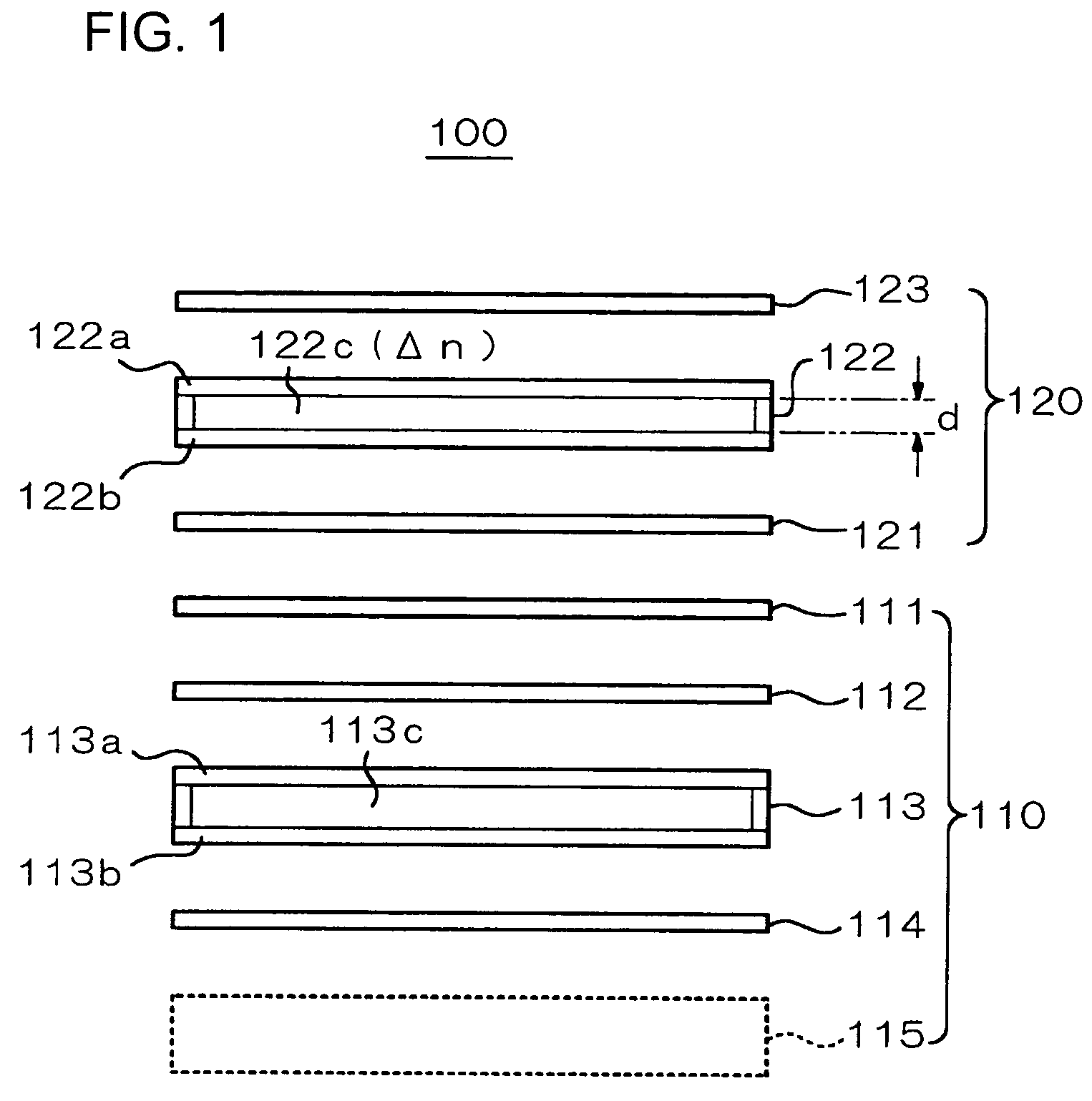
[0105]A display device according to a first embodiment of the invention will be described with reference to FIG. 5. This first embodiment is formed based on the first structural example, and in FIG. 5, non-essential components (for example, retardation plate and back light) are properly omitted, and the same reference marks are attached to the corresponding components of the first structural example.

[0106]In this embodiment, in the display unit 110, the polarizing plate 111, the liquid crystal panel 113, and the polarizing plate 114 are mutually held together in an integral way, and in the display switching unit 120, the reflective polarizing plate 121, the liquid crystal panel 122, and the polarizing plate 123 are mutually held together in an integral way. The integrated portion of the display unit 110 and the integrated portion of the display switching unit 120 are optically adhered to each other by an adhesive layer 131. Optical adhesion means that the display unit 110 is adhered...

second embodiment

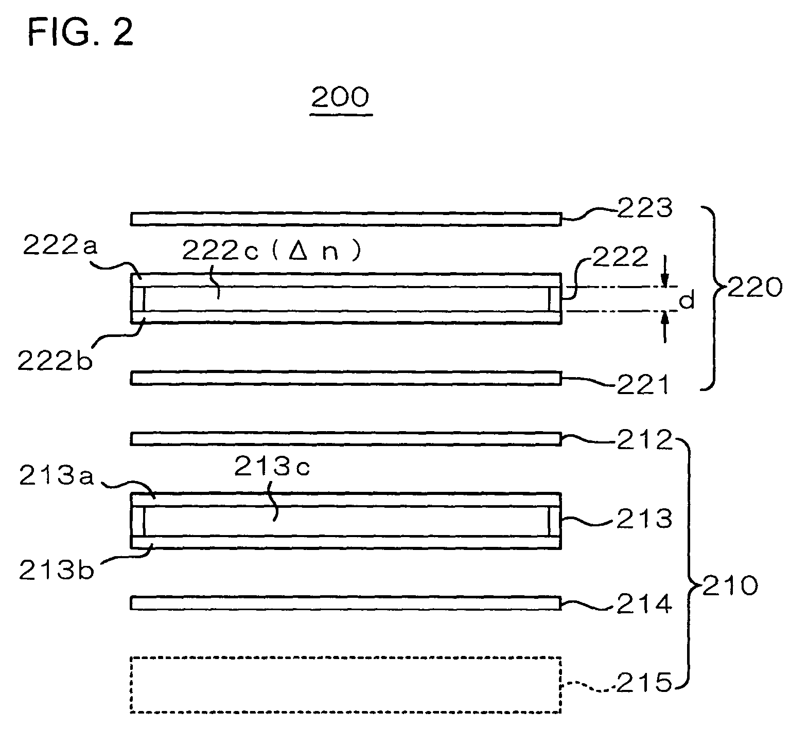
[0111]A display device according to a second embodiment of the invention will be described with reference to FIG. 6. The second embodiment is formed according to the second structural example as mentioned above. In this embodiment, the display unit 210 is not optically adhered to the display switching unit 220 (i.e., they are separated from each other), but they are firmly supported by a case or the like (not illustrated).

[0112]In the embodiment, an anti-reflection coating 232 is formed on the surface of the display unit 210 on the side of the display switching unit 220, and an anti-reflection coating 233 is formed on the surface of the display switching unit 220 on the side of the display unit 210. Further, an anti-reflection coating 234 is formed on the surface of the display switching unit 220 on the side opposite to the display unit 210 (on the observation side).

[0113]The above anti-reflection coatings (AR coatings) 232, 233, and 234 are formed by a single layer film coated in a...

third embodiment

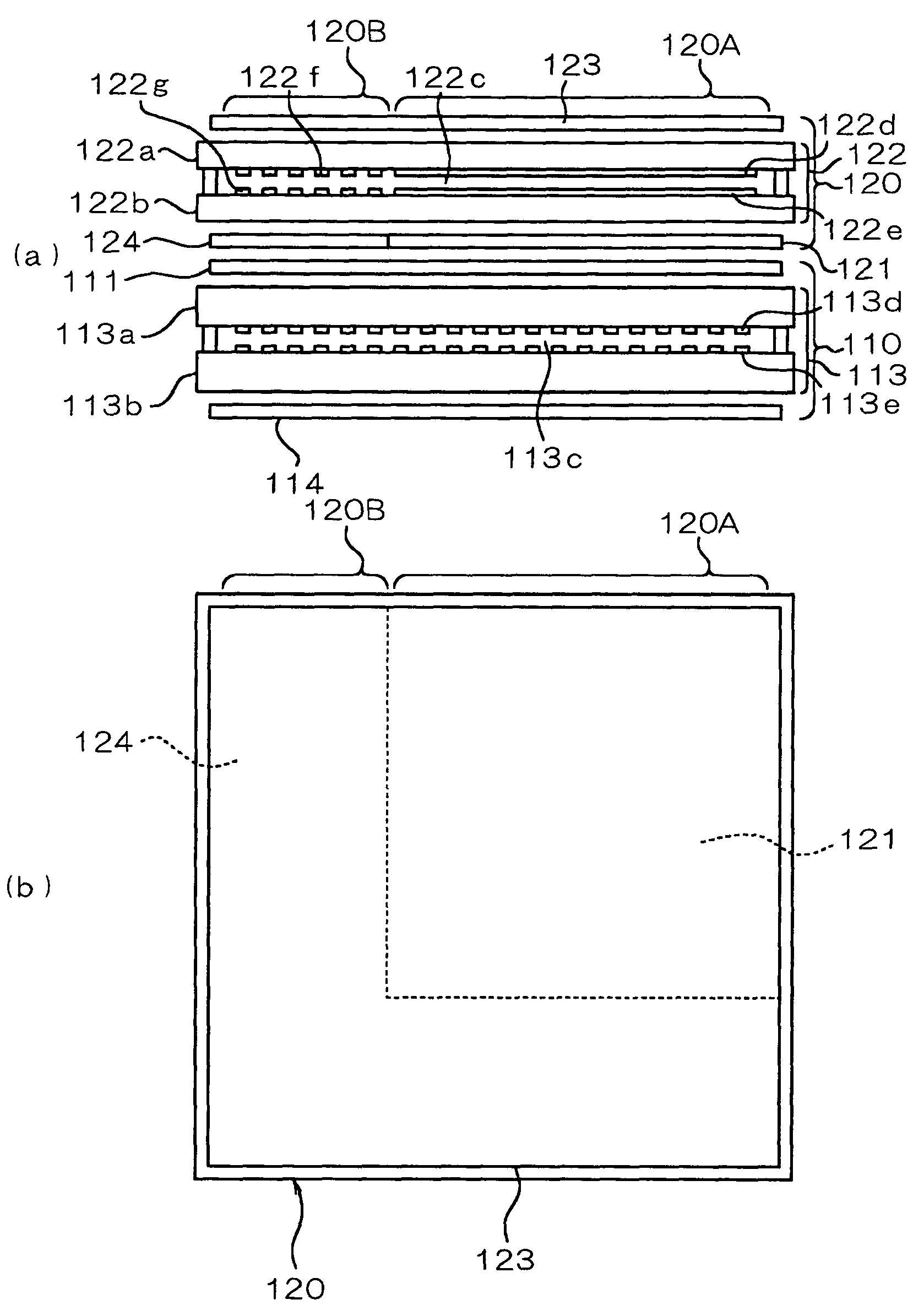
[0116]A third embodiment according to the invention will be described with reference to FIG. 7. The embodiment is formed according to the first structural example. In the embodiment, two regions 120A and 120B are provided in the display switching unit 120. In the region 120A, single electrodes 122d and 122e for applying an electric field to the liquid crystal layer 122c are formed entirely on the inner surfaces of the substrates 122a and 122b of the liquid crystal panel 122, and a single pixel is formed in the region 120A by these electrodes 122d and 122e. On the contrary, a plurality of electrodes 122f and 122g, smaller than the electrodes provided in the region 120A, are arranged in the region 120B, and a plurality of pixels are arranged there. Accordingly, in the region 120A, the optical state of the liquid crystal layer 122c is switched by the entire block, while in the region 120B, the optical state of the liquid crystal layer 122c can be controlled for every pixel formed by a ...


PUM

PropertyMeasurementUnit
thicknessaaaaaaaaaa
thicknessaaaaaaaaaa
temperatureaaaaaaaaaa

Abstract

A display device 100 has a display unit 110 and a display switching unit 120. The display switching unit 120 is provided with a reflective polarizing plate 121, a liquid crystal panel 122, and a polarizing plate 123 arranged in this order from the side of the display unit 110 to the observation side. By controlling the liquid crystal panel 122, the display switching unit can be switched between a light transmissive state and a light reflective state. The display unit 110 and the display switching unit 120 are optically adhered to each other by an adhesive layer 131. Thus, deterioration of the contrast by boundary reflection can be restrained, and the flatness and the rigidity of the device can be improved.

Description

BACKGROUND OF THE INVENTION[0001]1. Field of the Invention[0002]The present invention relates to a display device and electronic equipment having the same, and especially relates to a structure of a display body capable of switching a display screen into a mirror mode.[0003]2. Related Art[0004]Hitherto, there has been known a display device which is switchable between a normal display mode and a mirror mode by overlapping two liquid crystal panels. For example, there is a display device in which a display switching unit is provided on the observation side of the display unit having the same structure as that of a typical liquid crystal display device, and a reflective polarizing plate, a liquid crystal panel, and an absorptive polarizing plate are disposed in the display switching unit in this order from the side of the display unit. In this display device, the reflective polarizing plate of the display switching unit transmits the first polarization component and reflects the secon...

Claims


Application Information

Patent Timeline
Patent Type & Authority Patents(United States)
IPC IPC(8): G02F1/1335G02F1/133G02F1/1347G02F1/01G02F1/13363G02F1/1343G02F1/19
CPCG02F1/133536G02F1/1347G02F1/19G02F1/1335
Inventor KASAJIMA, YASUSHITSUCHIHASHI, TOSHIHIKOEISAKI, SAORIUSHIKI, TAKEYOSHIWADA, HIROSHIMAEDA, TSUYOSHI
Owner BOE TECH GRP CO LTD
Why Eureka
Try Eureka