Case for covering electronic parts and display apparatus including the same

a technology for electronic parts and display devices, applied in the direction of electrical apparatus casings/cabinets/drawers, identification means, semiconductor/solid-state device details, etc., can solve the problems of reducing air resistance, reducing air resistance, and reducing air resistan

Inactive Publication Date: 2007-09-11
SAMSUNG SDI CO LTD
View PDF23 Cites 35 Cited by
  • Summary
  • Abstract
  • Description
  • Claims
  • Application Information

AI Technical Summary

Benefits of technology

[0015]Preferably, entry holes having a width of 1-8 mm are formed in the entry portion, and exit holes having a width of 1-8 mm are formed in the exit portion. Preferably, the entry holes and the exit holes are formed in a predetermined pattern, and at least some of the entry holes and the exit holes are defined by a ...

Problems solved by technology

In an electronic device such as in a display apparatus, the electronic components generate a large amount of heat.
Often, space is too cramped to have a fan.
Fans are also expensive and draw more power.
In an essentially tw...

Method used


Image

  • Case for covering electronic parts and display apparatus including the same
  • Case for covering electronic parts and display apparatus including the same
  • Case for covering electronic parts and display apparatus including the same

Examples


first embodiment

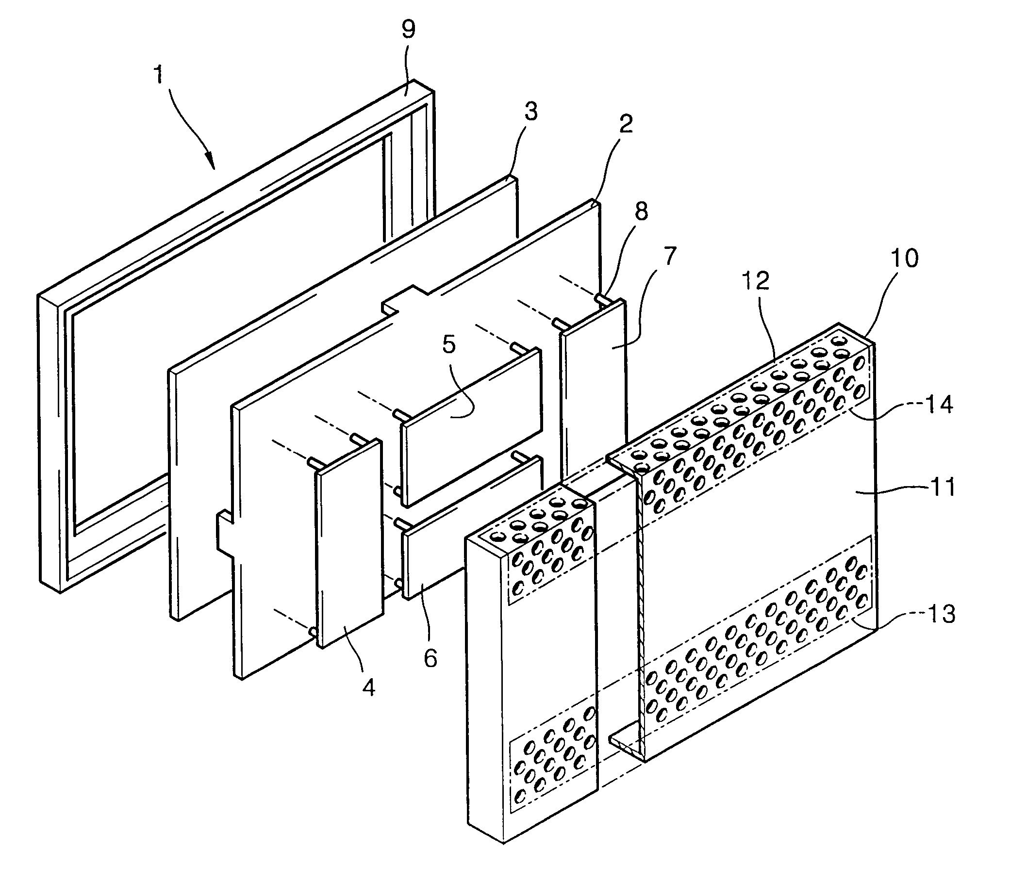
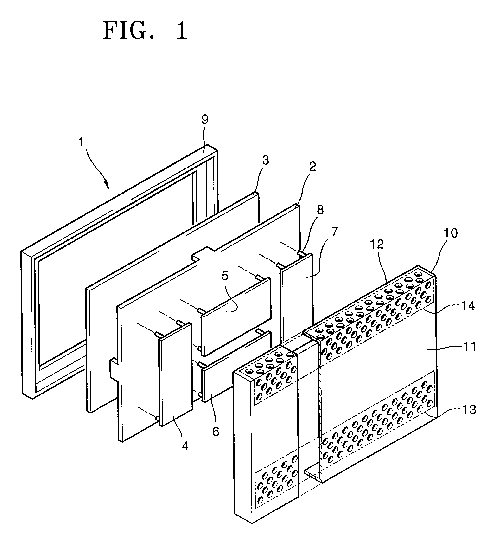
[0038]Turning to FIG. 3, FIG. 3 illustrates an exploded perspective view of a display apparatus 101 including a case for covering electronic parts according to the present invention. 3. For clarity of the description, it is assumed that the case covers a display panel 3 and accompanying parts. In FIG. 3, the display panel 3 and the accompanying parts are schematically illustrated and some other electronic parts are omitted for clarity.

[0039]The display apparatus 101 includes the display panel 3; the circuit boards 4, 5, 6, and 7 driving the display panel 3, the frame 2 supporting the display panel 3 and the circuit boards 4, 5, 6, and 7, the spacers 8 supporting the circuit boards 4, 5, 6, and 7 on the frame 2 and the front cover 9 and a rear cover 110, which constitute a case for covering the above members.

[0040]The display panel 3 displays an image which a user can view and may be a front panel of a cathode-ray tube (CRT), a liquid crystal display (LCD) panel, an electroluminescen...

second embodiment

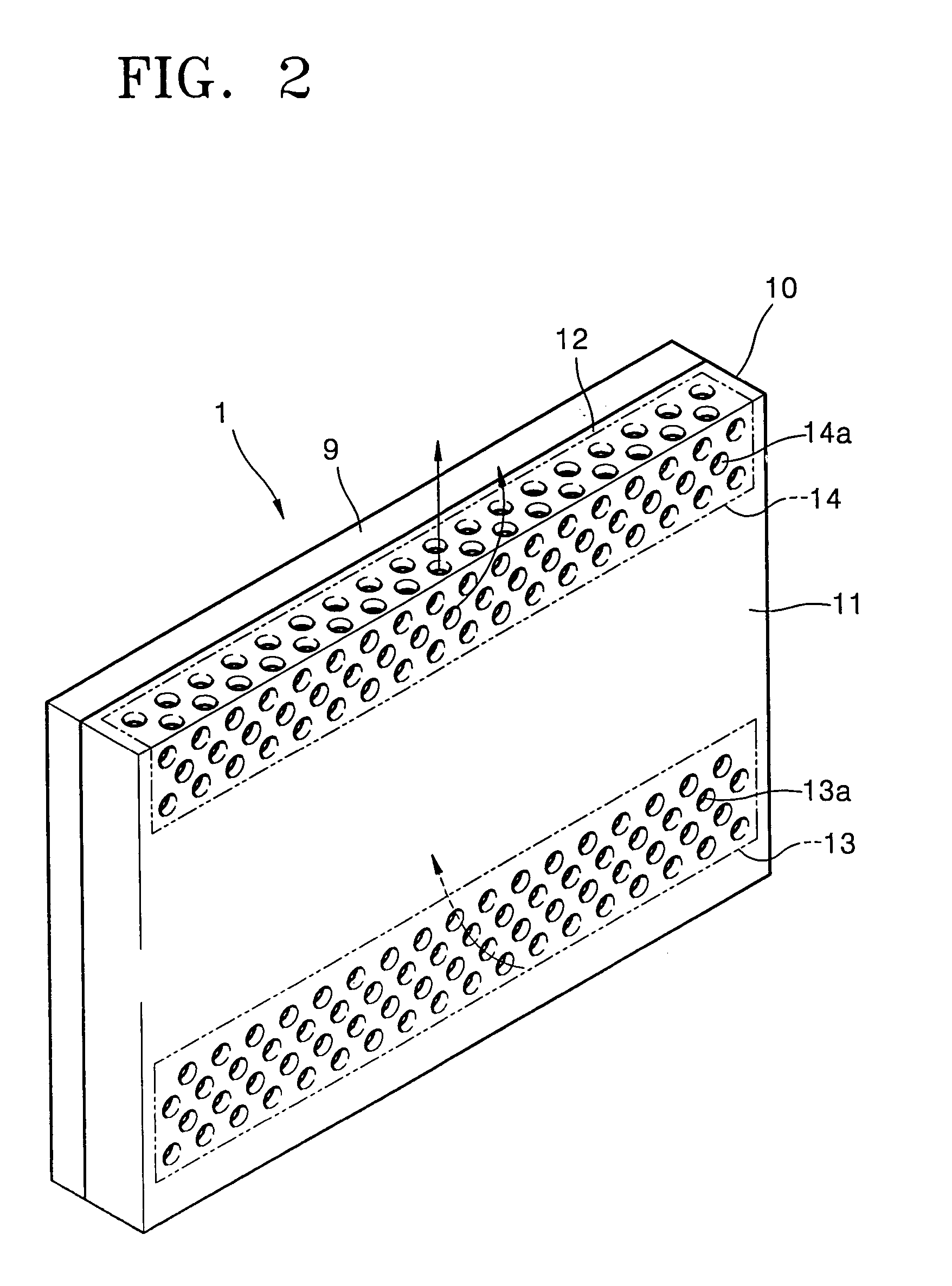
[0054]As illustrated by the arrows in FIG. 6, air flows in through the left and right entry portions 213A and 213B, absorbs heat from electronic parts, and flows out through the left and right exit portions 214A and 214B, separately. In the second embodiment, the inner space defined by the case is vertically separated into two spaces by the partition wall 220 but may be separated into three or more spaces. Thus, if left circuit board 4 generates an enormous amount of heat and right circuit board 7 generates a relatively small amount of heat, the air heated by left circuit board cannot reach the right circuit board 7 because of partition 220. Therefore, right circuit board 7 receives cool air of ambient temperature through right entry portion 213B and the cooling of right circuit board 7 is not compromised by the enormous amount of heat generated by left circuit board 4.

[0055]An exploded perspective view of a display apparatus 301 including a case for covering electronic parts accord...

fifth embodiment

[0060]Entry holes 513a, 515Aa, 515Ba, and 515Ca and exit holes 514Aa, 514Ba, 514Ca, and 516a are formed in the first entry portion 513, the first exit portions 514A, 514B, and 514C, the second entry portions 515A, 515B, and 515C, and the second exit portion 516 in order to allow air to flow in and out of the case. It is preferable that the entry holes 513a, 515Aa, 515Ba, and 515Ca and exit holes 514Aa, 514Ba, 514Ca, and 516a have shapes and sizes maximizing the flow of air, insofar as the structural strength of the rear cover 510 is guaranteed. Their shapes may be a circle, a rectangle, a diamond, a triangle, and a hexagon. Their sizes are preferably set to enable air to flow as efficiently as possible. Their sizes are determined as being small enough not to allow children's fingers to pass therethrough. Usually, the width of the entry and exit holes 513a, 515Aa, 515Ba, 515Ca, 514Aa, 514Ba, 514Ca, and 516a satisfying the above conditions is about 1-8 mm. In the fifth embodiment, the...


PUM


Abstract

A case for covering electronic parts and efficiently discharging heat generated from the electronic parts and a display apparatus including the case are provided. The case includes at least one partition wall partially separating at least an inner space of the case. An entry portion, through which air flows in, and an exit portion, through which the air having flowed in through the entry portion and then having absorbed heat from the electronic parts flows out, are formed in each plane of the case. Each plane is separated by the partition wall.

Description

CLAIM OF PRIORITY[0001]This application claims the is incorporated herein in its entirety by reference. This application makes reference to, incorporates the same herein, and claims all benefits accruing under 35 U.S.C. §119 from Korean Patent Application No. 2002-50523, filed on Aug. 26, 2002.BACKGROUND OF THE INVENTION[0002]1. Field of the Invention[0003]The present invention relates to a case for covering electronic parts and a display apparatus including the same, and more particularly, to a case having a structure for improving the radiation of heat generated from electronic parts, and a display apparatus including the same.[0004]2. Description of the Related Art[0005]In an electronic device such as in a display apparatus, the electronic components generate a large amount of heat. It is important to dissipate this heat in an efficient manner so that the electronic components do not overheat. Often, space is too cramped to have a fan. Fans are also expensive and draw more power....

Claims


Application Information

Patent Timeline
IPC IPC(8): H05K7/20F28F7/00G02F1/1333G02F1/13G02F1/133G06F1/16G06F1/20G09F9/00H01L23/34H04N5/64H04N5/645H05K5/02
CPCG06F1/1601G06F1/203H05K5/0213H05K7/20127H05K7/20954G02F1/133308G02F1/133382G02F2201/36G06F2200/1612H01L2924/0002H01L2924/00H04N5/645
Inventor RYU, HO-CHULBAE, SUNG-WON
Owner SAMSUNG SDI CO LTD
Why Eureka
Try Eureka