Ultrasonic transmitter, ultrasonic transceiver and sounding apparatus

a transceiver and ultrasonic technology, applied in the direction of sonic/ultrasonic/infrasonic transmission, mechanical vibration separation, instruments, etc., can solve the problems of extreme difficulty in defining circuit design, extreme difficulty in configuring a system which meets all these requirements, and achieves easy suppression of harmonic emissions and high efficiency

Inactive Publication Date: 2007-09-11
FURUNO ELECTRIC CO LTD
View PDF8 Cites 5 Cited by
  • Summary
  • Abstract
  • Description
  • Claims
  • Application Information

AI Technical Summary

Benefits of technology

[0025]It is an object of the invention to provide an ultrasonic transmitter which can transmit ultrasonic waves at high efficiency and easily suppress harmonic emissions with a small number of components. It is a further object of the invention to provide an ultrasonic transceiver employing such an ultrasonic transmitter as well as a sounding apparatus employing such an ultrasonic transceiver.
[0027]In this construction, the switching frequency fa is matched to the transmitting frequency fs when the ultrasonic signals are transmitted at maximum output power so that power loss due to switching operation of the switching devices is suppressed. When the output power of the ultrasonic signals is reduced, on the other hand, the switching frequency fa is made higher than the transmitting frequency fs so that the switching frequency fa is separated far away from the transmitting frequency fs. Harmonic components are dependent on the switching frequency fa. Consequently, it is possible to suppress the occurrence of unremovable harmonics having frequencies close to the transmitting frequency fs. In addition, it is possible to relatively reduce power loss due to switching operation even when the switching devices are switched at a high frequency, because the output power of the ultrasonic signals is reduced in this case.
[0029]The ultrasonic transmitter thus constructed employing the half-bridge circuits makes it possible to generate the driving pulse signal with a small number of components. Also, this construction makes it possible to easily vary the switching frequency fa and the ON periods of the switching devices according to desired amplitudes of the ultrasonic signals using the reference signal of which frequency ff is higher than the switching frequency fa. As a consequence, a low-pass filter for suppressing harmonics can be easily configured since the occurrence of such spurious emissions (e.g., the second harmonic) that are difficult to remove is avoided by making the switching frequency fa higher than the transmitting frequency fs when the output power of the ultrasonic signals is reduced. When the output power of the ultrasonic signals is at a maximum, on the other hand, the switching frequency fa is lowered down to the transmitting frequency fs. Even when the switching frequency fa is lowered to the transmitting frequency fs at the maximum output power, the driving signal is not made of extremely narrow pulses having a period Ts so that the occurrence of harmonics is suppressed. Additionally, since the switching frequency fa of the switching devices lowers in this case, it is possible to prevent power loss due to heat generation caused by the switching operation.
[0034]Overall, the present invention makes it possible to configure a compact and low-cost ultrasonic transmitter capable of generating driving signals of which amplitudes are controlled by pulse-width modulation (PWM), the ultrasonic transmitter including in a transmitting beamformer thereof half-bridge circuits. In this ultrasonic transmitter, switching devices of each half-bridge circuit are switched at the frequency of the driving signal based on a specific reference signal when the level of the driving signal is maximized, whereas the switching devices of each half-bridge circuit are switched at a switching frequency which is higher than the frequency of the driving signal using the frequency of a clock signal which is higher than the frequency of the driving signal as a reference when the level of the driving signal is reduced, to generate the driving signals at high efficiency.
[0035]In addition, the invention provides a compact and low-cost sounding apparatus which can successively scan desired sounding directions, obtain received echo data derived from a particular search area based on echo signals received from the individual sounding directions, and display the received echo data to enable an operator to accurately recognize a detected echo image for multiple sounding directions substantially at the same point in time. Such a sounding apparatus can be configured by employing the aforementioned ultrasonic transceiver including the transmitting beamformer and the receiving beamformer.

Problems solved by technology

An ultrasonic transmitter employing the aforementioned type of full-bridge circuit has a problem in that the number of components increases due to the need for four switching devices in each full-bridge circuit and circuit configuration becomes complicated, resulting in an eventual increase in product cost.
While almost all of these harmonic components can be suppressed by using a low-pass filter, the second harmonic component can only be removed by use of an additional filter having a high Q factor, rendering circuit design extremely difficult.
It is extremely difficult to configure a system which satisfies all these requirements.
Even if it is at all possible to design such a system, a series of complicated adjustments would be necessary in manufacturing the system, causing an increase in work load.
However, because the frequency fc of the ramp signal and the frequency fa of the driving pulse signal determined by the ramp signal are higher than the frequency fs of the ultrasonic signal, output efficiency decreases as a result of an increase in power loss due to heat generation by the switching devices Q1, Q2 when the half-bridge circuit is operated at the maximum output power.

Method used


Image

  • Ultrasonic transmitter, ultrasonic transceiver and sounding apparatus
  • Ultrasonic transmitter, ultrasonic transceiver and sounding apparatus
  • Ultrasonic transmitter, ultrasonic transceiver and sounding apparatus

Examples


Embodiment Construction

[0050]A scanning sonar including an ultrasonic transceiver according to a preferred embodiment of the invention is now described referring to the appended drawings.

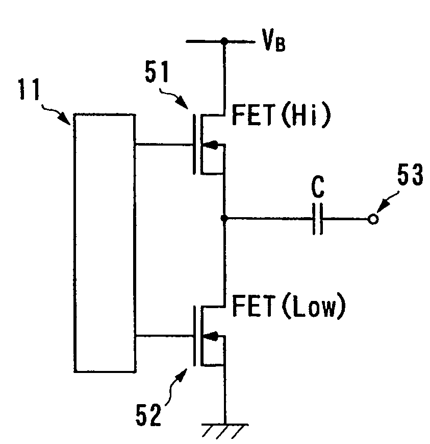
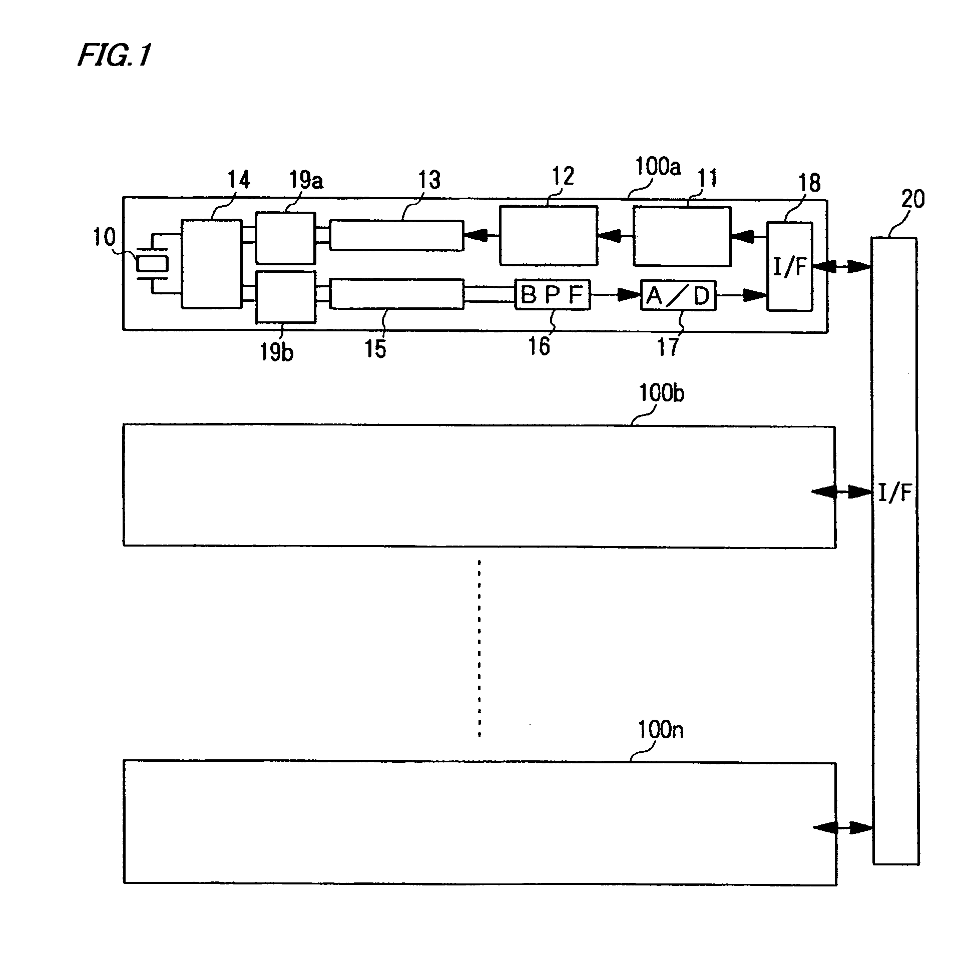
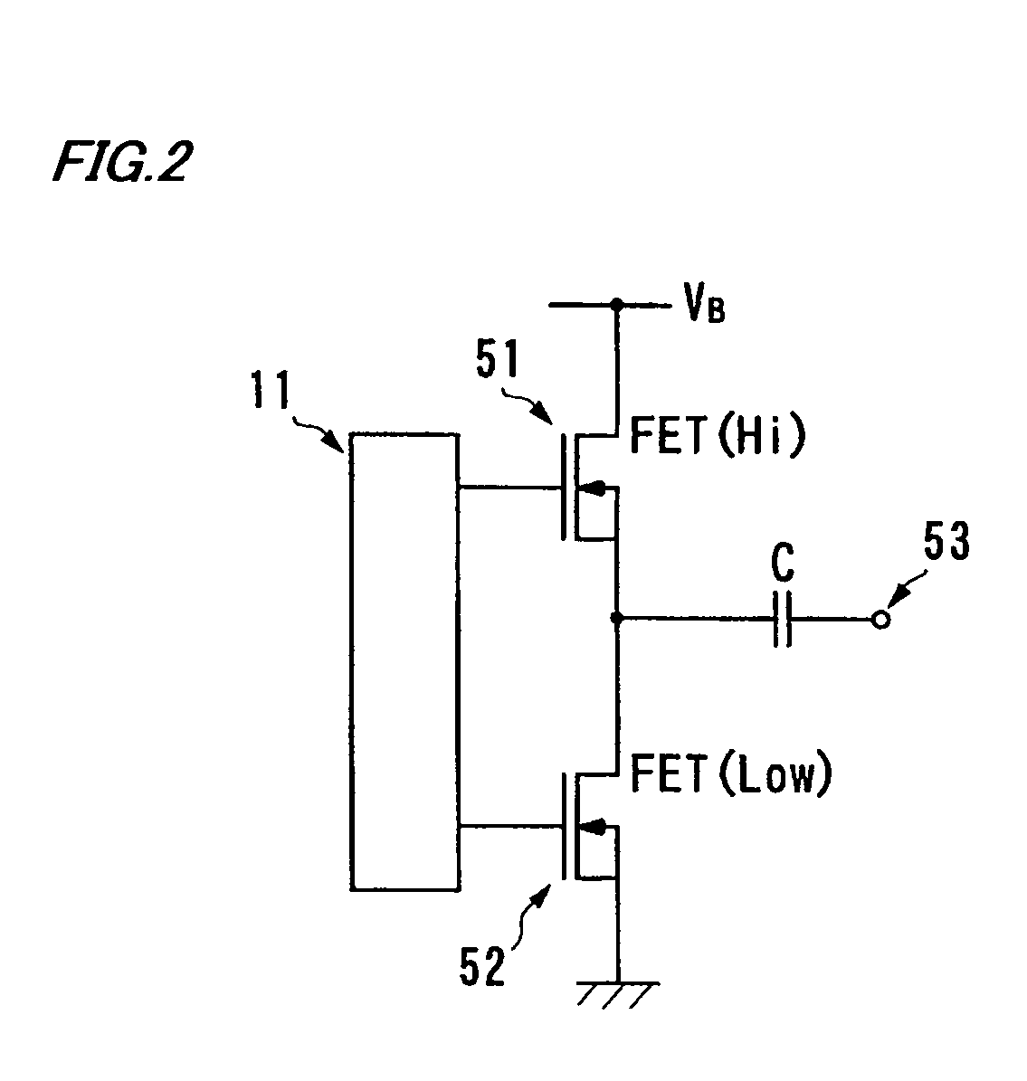
[0051]FIG. 1 is a block diagram generally showing the configuration of transmit-receive channels 100 of the scanning sonar according to the embodiment. Referring to FIG. 1, each of the transmit-receive channels 100 includes a driver interface 11 which generates drive signals for controlling a driver circuit 12 based on a clock signal (which corresponds to a reference signal referred to in claim 2 of this invention) and a digital-formatted control signal for controlling switching operation supplied from a later-described programmable transmitting beamformer 26. The aforementioned drive signals are for performing pulse-width modulation (PWM) and these drive signals are produced through a digital process. When an analog process is used in performing pulse-width modulation, the drive signals are produced based on a comparison...


PUM


Abstract

A driver circuit for generating a driving signal by pulse-width modulation (PWM) includes a half-bridge circuit formed essentially of a pair of series-connected FETs. When the level of an ultrasonic signal, or of the driving signal, is to be maximized, the individual FETs are switched at a switching frequency matched to the frequency of the driving signal. When the level of the ultrasonic signal, or the driving signal is to be reduced, on the other hand, the individual FETs are switched with specific timing determined based on the frequency of a clock signal of which period is shorter than that of the driving signal.

Description

[0001]This Non-Provisional application claims priority under 35 U.S.C. §119(a) on Patent Application No(s). 2003-158239 filed in JAPAN on Jun. 3, 2003, the entire contents of which are hereby incorporated by reference.BACKGROUND OF THE INVENTION[0002]1. Field of the Invention[0003]The present invention relates to an ultrasonic transmitter for radiating ultrasonic waves, an ultrasonic transceiver for radiating ultrasonic waves and receiving echoes of the radiated ultrasonic waves, and a sounding apparatus including an ultrasonic transceiver for detecting objects using ultrasonic waves.[0004]2. Description of the Related Art[0005]Today, ultrasonic sounding apparatuses, such as scanning sonars, are widely used for detecting underwater objects (targets). A scanning sonar for detecting underwater objects in all surrounding directions has a generally cylindrical transducer. The scanning sonar forms an ultrasonic transmitting beam oriented in all directions around the transducer by activat...

Claims


Application Information

Patent Timeline
Patent Type & Authority Patents(United States)
IPC IPC(8): H04B1/02G01S15/42B06B1/02G01S7/523G01S7/524
CPCB06B1/0223G01S7/524B06B1/0215
Inventor NISHIDA, MASARU
Owner FURUNO ELECTRIC CO LTD
Why Eureka
Try Eureka