
Method and apparatus for an adaptive rate control mechanism reactive to flow control messages in a packet switching system

a packet switching system and flow control technology, applied in data switching networks, frequency-division multiplexes, high-level techniques, etc., can solve problems such as internal congestion, poor traffic throughput, and high cost of non-blocking packet switching fabrics

Active Publication Date: 2007-09-11
CISCO TECH INC
View PDF32 Cites 34 Cited by
  • Summary
  • Abstract
  • Description
  • Claims
  • Application Information

AI Technical Summary

Benefits of technology

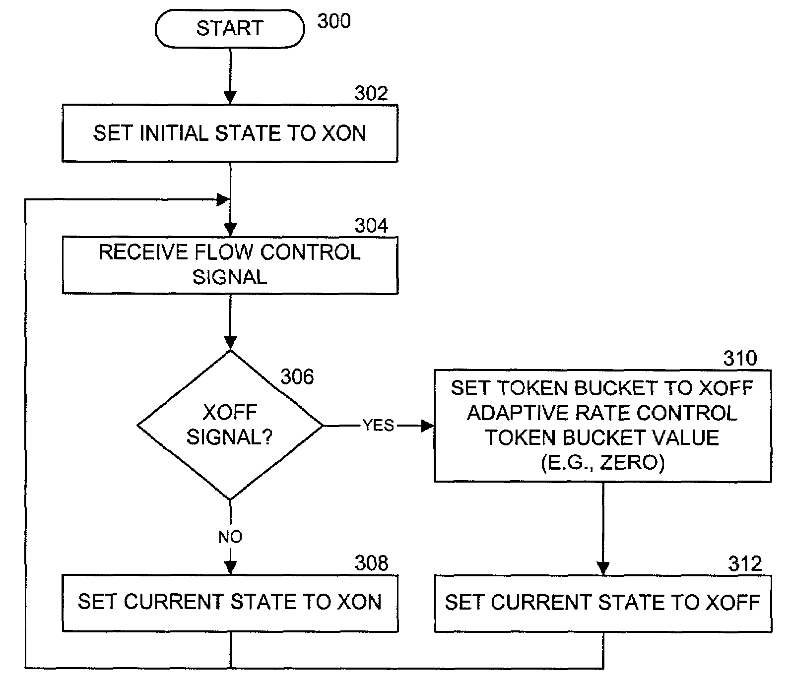
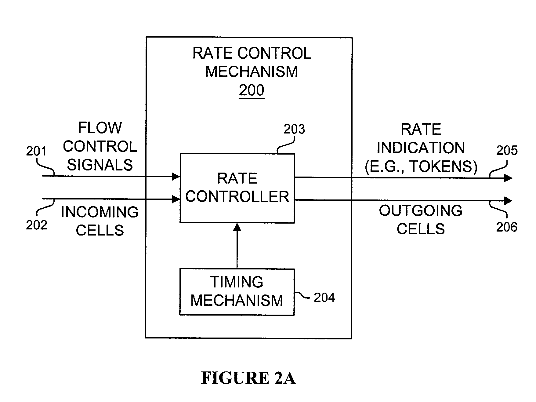
[0005]Systems and methods are disclosed for an adaptive rate control mechanism reactive to flow control messages in a packet switching system. One embodiment receives a start flow control signal and a stop flow control s

Problems solved by technology

As non-blocking packet switching fabrics are typically expensive and non-scalable to large packet switching systems, many packet switching fabrics are designed such that internal congestion might arise depending on traffic loads and patterns.
However, known methods of reacting to flow controls signals can lead to poor traffic throughput, such as that produced by a synchronized on and off oscillation of sending sources.
This creates a bottleneck where traffic becomes backlogged behind the congestion point.
Another problem that can occur is if the occupancy drains too quickly before traffic can be resumed.
This can cause underrun and effective loss of speedup through the fabric.
Known systems and methods do not adequately react to traffic conditions.

Method used


Image

  • Method and apparatus for an adaptive rate control mechanism reactive to flow control messages in a packet switching system
  • Method and apparatus for an adaptive rate control mechanism reactive to flow control messages in a packet switching system
  • Method and apparatus for an adaptive rate control mechanism reactive to flow control messages in a packet switching system

Examples


Embodiment Construction

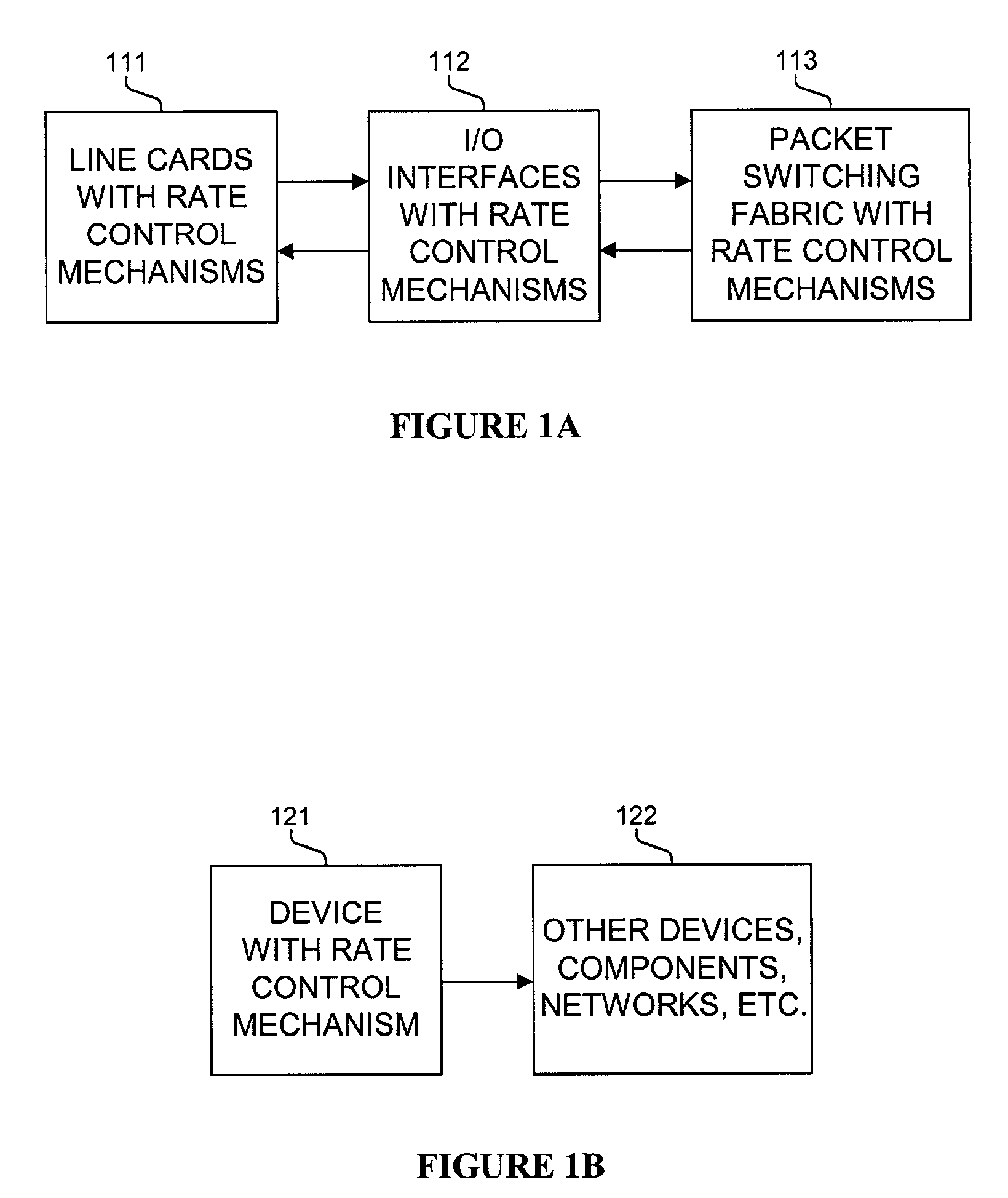
[0010]Methods and apparatus are disclosed for an adaptive rate control mechanism reactive to flow control messages in a packet switching system which also may be used, inter alia, in other computer and communications systems, including, but not limited to a router or network. Such methods and apparatus are not limited to a single computer or communications system. Rather, the architecture and functionality taught herein are extensible to an unlimited number of computer and communications systems, devices and embodiments in keeping with the scope and spirit of the invention. Embodiments described herein include various elements and limitations, with no one element or limitation contemplated as being a critical element or limitation. Each of the claims individually recite an aspect of the invention in its entirety. Moreover, some embodiments described may include, but are not limited to, inter alia, systems, integrated circuit chips, embedded processors, ASICs, methods, and computer-r...


PUM


Abstract

Methods and apparatus are disclosed for an adaptive rate control mechanism reactive to flow control messages in a packet switching system and other communications and computer systems. Typically, a multiplicative increase and exponential decrease technique is used to throttle traffic. Backpressure feedback is used to calculate the initial rate at which to allow traffic after backpressure is deasserted. This reduces the probability of underrun of buffers (e.g., too little traffic being carried). The adjustment to the initial rate is made by measuring the time between the XON and XOFF in factor periods. Then a target XON time is subtracted. If the result is positive (i.e., the measured XON time was too long), the rate is multiplicatively increased (e.g., by a factor of two to the difference). If the result is negative (i.e., the measured XON time was too short), the rate is exponentially decreased (e.g., by the square root).

Description

FIELD OF THE INVENTION[0001]This invention relates to packet switching systems; and more particularly, the invention relates to an adaptive rate control mechanism reactive to flow control messages in a packet switching system.BACKGROUND OF THE INVENTION[0002]The communications industry is rapidly changing to adjust to emerging technologies and ever increasing customer demand. This customer demand for new applications and increased performance of existing applications is driving communications network and system providers to employ networks and systems having greater speed and capacity (e.g., greater bandwidth). In trying to achieve these goals, a common approach taken by many communications providers is to use packet switching technology.[0003]Consumers and designers of these systems typically desire high reliability and increased performance at a reasonable price. As non-blocking packet switching fabrics are typically expensive and non-scalable to large packet switching systems, ma...

Claims


Application Information

Patent Timeline
IPC IPC(8): H04L12/26
CPCH04L47/10H04L47/215H04L47/266Y02B60/31Y02D30/50
Inventor WILLIAMS, JR., JOHN J.DEJANOVIC, THOMAS
Owner CISCO TECH INC
Learn More