Ion engine grid arcing protection circuit

a protection circuit and engine technology, applied in the direction of machines/engines, marine propulsion, vessel construction, etc., can solve the problems of additional damage to the screen and accelerator grid, electrical plasma arcs that occur occasionally between the screen and the accelerator grid, and the normal erosion of the accelerator grid, etc., to reduce or eliminate the damage to the grid caused by the arc

Inactive Publication Date: 2007-09-18
L 3 COMM ELECTRON TECH
View PDF11 Cites 17 Cited by
  • Summary
  • Abstract
  • Description
  • Claims
  • Application Information

AI Technical Summary

Benefits of technology

[0008]In accordance with the present invention, a circuit is provided that couples to the accelerator grid of an ion engine in such a way that the voltage differential, and hence, the energy contained in a plasma arc occurring between the screen grid and the accelerator grid of the engine, is minimized, thereby reducing or eliminating the damage to the grids caused by the arc.
[0009]In a first exemplary embodiment thereof, the novel grid arcing protection circuitry includes a protection circuit that comprises a fixed impedance in series between the accelerator grid and the output of the internal accelerator power source within the ion thruster. During an arc between the accelerator grid and screen grid of the ion thruster, the added impedance causes a rapid reduction in the voltage of the accelerator grid relative to that of the screen grid.
[0010]While it is desirable to have the added impedance present in the arc protection circuit during normal operation of the ion engine, it may be desirable to reduce its impedance during startup of the engine, so that the accelerator grid current can quickly achieve a relatively high startup level for a brief period of time required for the engine to start. For this purpose, the arcing protection circuit further includes a circuit for selectably coupling the impedance into and out of the accelerator grid-to-accelerator-supply output path, and in one possible embodiment, this impedance coupling circuit may comprise a simple relay.
[0012]In an alternative exemplary embodiment, the grid arcing protection circuit can advantageously incorporate, in addition to the above accelerator grid monitoring circuit of the first embodiment, a variable impedance in place of the fixed impedance. As in the first embodiment, this impedance is coupled in series between the accelerator grid and the output of the internal accelerator power source within the ion thruster, the difference in this embodiment being that the impedance is variable. During a plasma arc between the screen and accelerator grids, the plasma arc causes the impedance of the circuit to increase rapidly. This action quickly reduces the relative voltage difference between the accelerator grid and the screen grid, thereby extinguishing or substantially limiting the energy of the arc almost instantaneously.
[0013]Advantageously, the accelerator grid voltage is regulated at the required voltage by the accelerator grid monitoring circuit, while the variable impedance is in series with the accelerator grid, by an error amplifier, which senses the voltage at the accelerator grid and provides a feedback signal proportional to the accelerator grid voltage that enables the magnitude of the internal accelerator power source within the ion thruster to be varied so as to maintain the accelerator grid at its required voltage during normal operation.
[0014]In one advantageous embodiment thereof, the variable impedance comprises an electrically actuated switch. The active switch may comprise a plurality of first transistors, which may be MOSFETs or Bipolar Junction Transistors, (“BJTs”), coupled in series between the accelerator grid and the output of the internal accelerator power source within the ion thruster. These transistors have their respective bases coupled in parallel and biased such that they operate in the fully saturated mode during normal thruster operation. A second transistor is coupled between the bases of the first transistor and the output of the internal accelerator power source within the ion thruster. A pulse transformer is also included, which has a primary winding coupled in series between the accelerator grid and the collector of the first transistor in the variable impedance string of transistors. The excess current during a plasma arc is sensed by the pulse transformer, with the secondary of the pulse transformer connected directly to the second transistor and a base circuit of the second transistor. The second transistor is coupled between the bases of the first transistors in the variable impedance string, which is connected to the internal accelerator power source within the ion thruster; the action of the pulse transformer being used to turn off all of the transistors in the variable impedance string rapidly. This action quickly reduces the voltage difference between the accelerator grid relative to the screen grid, thereby almost instantaneously extinguishing or substantially limiting the energy of the arc.

Problems solved by technology

Thus, while ion engines may lack the large thrust necessary to lift a heavy payload into orbit, they nevertheless have wide application in deep space missions, such as interplanetary exploration, and in orbital satellites for orbital positioning and attitude control, where engine “burns” may last for days, weeks, or even years.
During operation of the engine, the accelerator grid is normally subject to some erosion caused by “charge-exchange” ions.
In addition to this “normal” type of wear of the engine, electrical plasma arcs occasionally occur between the screen and accelerator grids.
These arcs are caused by various operational anomalies occurring in the engine, and can cause additional damage to the screen and accelerator grids over and above that caused by the normal charge-exchange ion erosion described above.
This additional type of damage to the grids has been shown to make the occurrence of plasma arcs between the grids more frequent by degrading the high voltage integrity of the screen-grid-to-accelerator-grid interface.
Such damage can result in a substantial reduction in the reliability and operational life of the engine.

Method used


Image

  • Ion engine grid arcing protection circuit
  • Ion engine grid arcing protection circuit
  • Ion engine grid arcing protection circuit

Examples


first embodiment

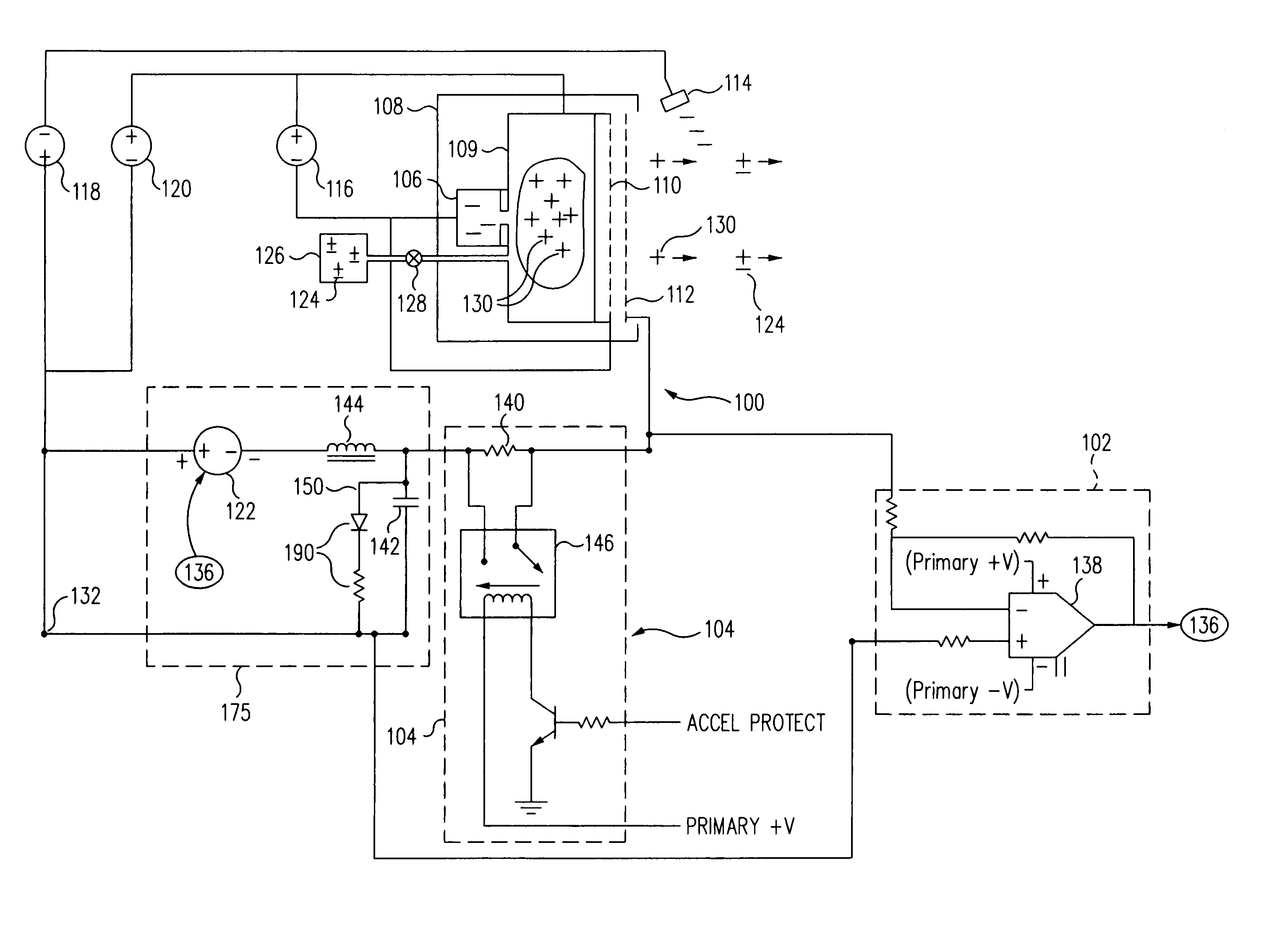
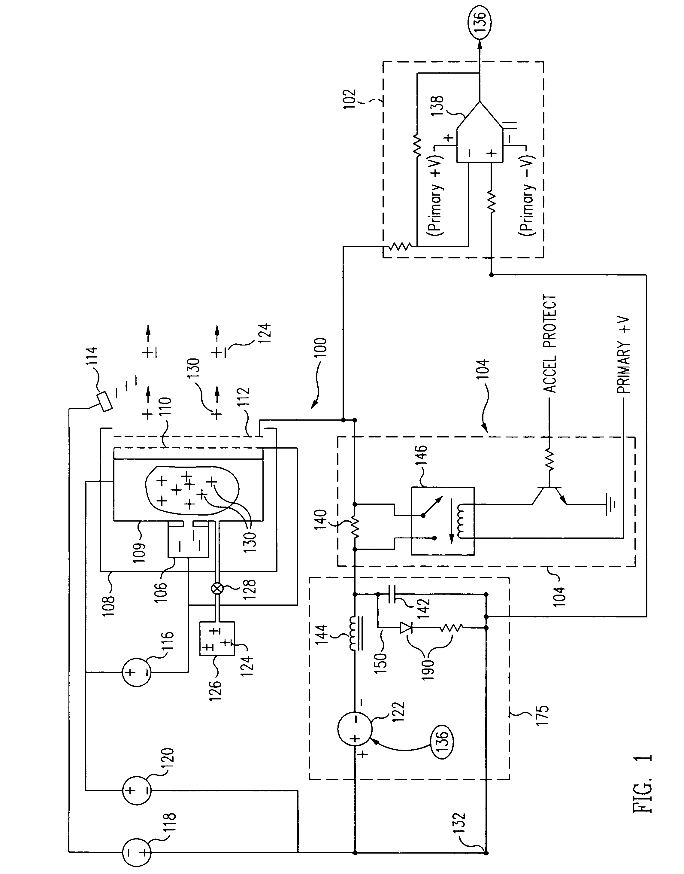
[0021]During operation of the ion engine 100, plasma arcs can occur between the screen and accelerator grids 110, 112. These arcs are caused by various operational anomalies occurring in the engine, and can cause additional damage to the screen and accelerator grids over and above that caused by the normal charge-exchange ion erosion described above. This additional type of damage to the grids has been shown to make the occurrence of plasma arcs between the grids more frequent by degrading the high voltage integrity of the screen-grid-to-accelerator-grid interface. Such damage can result in a substantial reduction in the reliability and operational life of the engine. a grid arcing protection circuit, comprising two parts 102 and 104, for preventing or reducing this type of damage to the grids is outlined by the dashed lines of FIG. 1.

[0022]As illustrated in FIG. 1, in addition to a monitoring and sensing circuit 102 above, there is an arc protection circuit 104. The arc protection ...

second embodiment

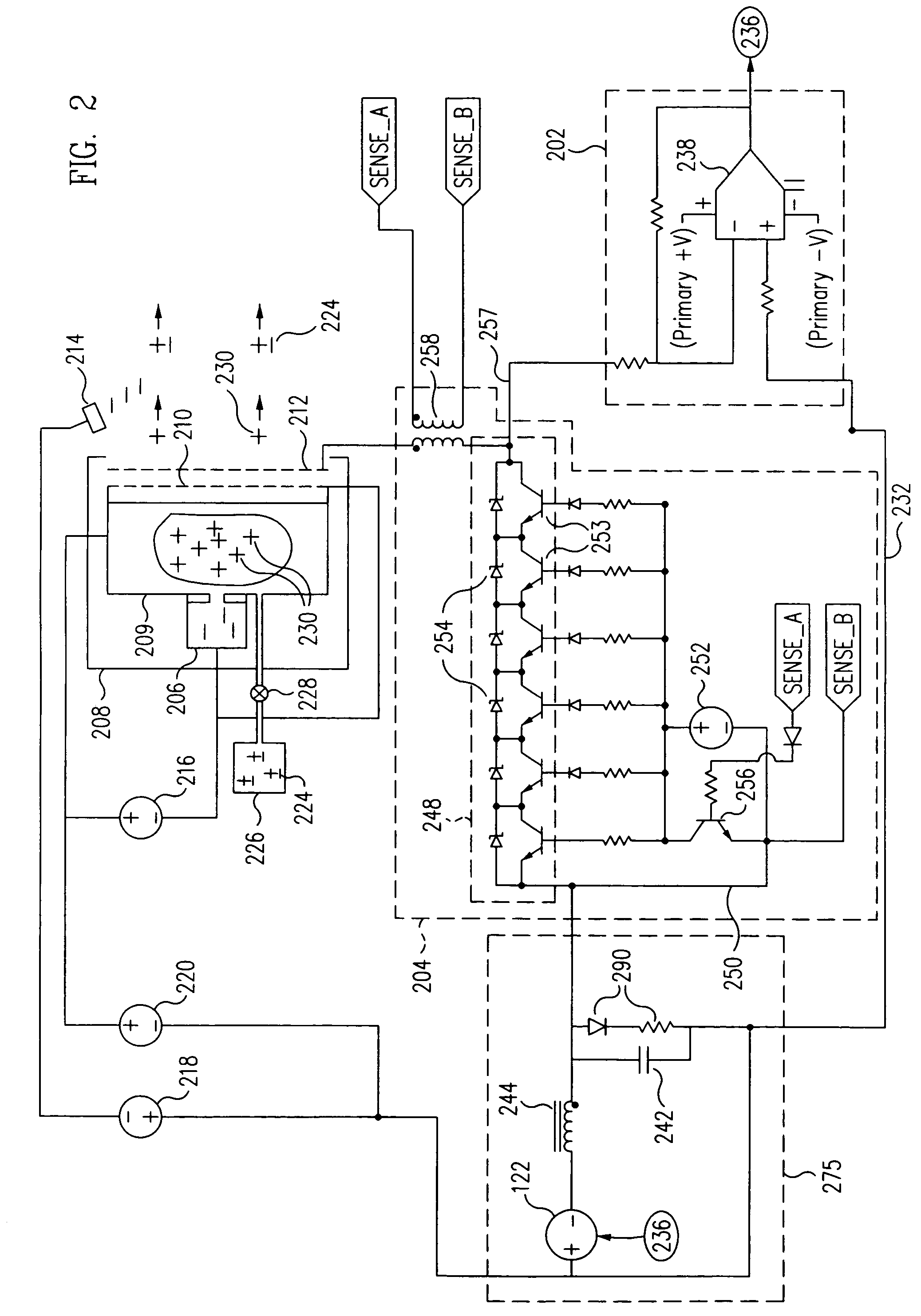
[0027]As will by now be evident to persons of skill in this art, many modifications, substitutions and variations can be made in and to the materials, configurations and methods of implementation of the grid arcing protection circuit of the present invention without departing from its spirit and scope. For example, the first transistors 253 of the switch 248 of the second embodiment may be implemented either as BJTs or as MOSFETs, depending on the speed, current and voltage requirements of the particular problem at hand. Accordingly, the scope of the present invention should not be limited to the particular embodiments illustrated and described herein, as they are merely exemplary in nature, but rather, should be fully commensurate with that of the claims appended hereafter and their functional equivalents.


PUM


Abstract

An arcing protection circuit for the screen and accelerator grids of an ion thruster engine includes an impedance, which in one embodiment, is fixed, and in another, is variable, coupled in series between the accelerator grid of the engine and a current return path of the grid in such a way that an increase in accelerator grid current resulting from a plasma arc occurring between the screen grid and the accelerator grid is converted by the impedance into a rapid reduction in the voltage difference between the screen and accelerator grids, thereby extinguishing the arc. The arcing protection circuit also includes a monitoring circuit coupled to the accelerator grid that senses an increase in the voltage on the accelerator grid resulting from the plasma arc, and in response thereto, causes the accelerator grid power supply to reduce the voltage on the accelerator grid.

Description

BACKGROUND OF THE INVENTION[0001]1. Field of the Invention[0002]This invention relates to ion thruster engines in general, and in particular, to a circuit that couples to the accelerator grid of an ion engine in such a way that the voltage difference, and hence, the energy contained in a plasma arc occurring between the screen grid and the accelerator grid of the engine, is minimized, thereby reducing or eliminating the damage to the grids caused by such arcing.[0003]2. Related Art[0004]In accordance with well-known Newtonian principles, if electrically charged particles, or ions, are accelerated to a high velocity in a vehicle and then discharged from it, the vehicle will be propelled in a direction opposite to that of the discharged particles, thus giving rise to the development of “electrostatic,” or “ion thruster” engines for space vehicles. While such engines can produce only a very small amount of thrust compared to that produced by the larger and more familiar chemical rocket...

Claims


Application Information

Patent Timeline
Patent Type & Authority Patents(United States)
IPC IPC(8): F03H1/00
CPCF03H1/0043
Inventor WISEMAN, STEVEN L.
Owner L 3 COMM ELECTRON TECH
Why Eureka
Try Eureka