Out-of-position friction stir welding of high melting temperature alloys

a high melting temperature alloy and friction stir technology, applied in the field of friction stir welding, can solve the problems of compromising welds, no tool that is capable of functional welding materials having higher melting points, and depletion of non-metallic reinforcement materials which have been joined with original workpiece materials to create alloys at welds

Inactive Publication Date: 2007-09-18
BRIGHAM YOUNG UNIV +1
View PDF82 Cites 47 Cited by
  • Summary
  • Abstract
  • Description
  • Claims
  • Application Information

AI Technical Summary

Problems solved by technology

Thus, while friction stir welding is a very advantageous technique for welding non-ferrous alloys such as aluminum, brass and bronze, there has been no tool that is capable of functionally welding materials having higher melting points.
Unfortunately, fusion welding alters or damages the alloy at the weld, thereby compromising the weld as a result of the defects or adverse phases which form in the weld during the welding process.
In some cases, the non-metallic reinforcement material which has been joined with the original workpiece material to create the alloy is depleted at the weld.
Most tools simply do not work at all in MMCs, ferrous alloys, and superalloys.
If a conventional tool could begin friction stir welding, the wear would be so significant that a probe would be torn apart after only a short distance.
For example, some alloys will cause wear on a probe such that it can no longer function after welding for a distance of only inches.
Unfortunately, it is generally the case that it is not possible to simply insert a new tool and begin the friction stir welding process where the previous probe failed.
If the weld is not continuous and uninterrupted, it is useless because of mechanical weakness.
Furthermore, a portion of the tool is typically left behind in the workpiece material, also contributing to the mechanical weakness.
MMCs have desirable stiffness and wear characteristics, but they also have a low fracture toughness, thereby limiting applications.
There are significant challenges that have so far prevented the creation of a tool that can functionally weld MMCs, ferrous alloys, and superalloys.

Method used


Image

  • Out-of-position friction stir welding of high melting temperature alloys
  • Out-of-position friction stir welding of high melting temperature alloys
  • Out-of-position friction stir welding of high melting temperature alloys

Examples


Embodiment Construction

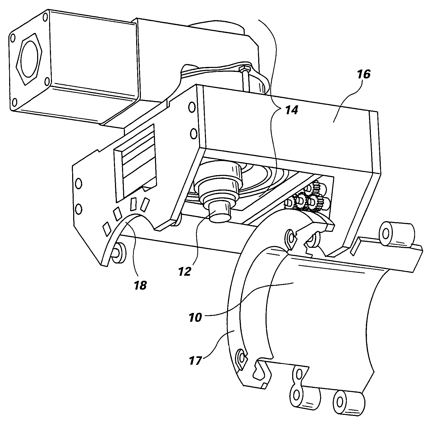
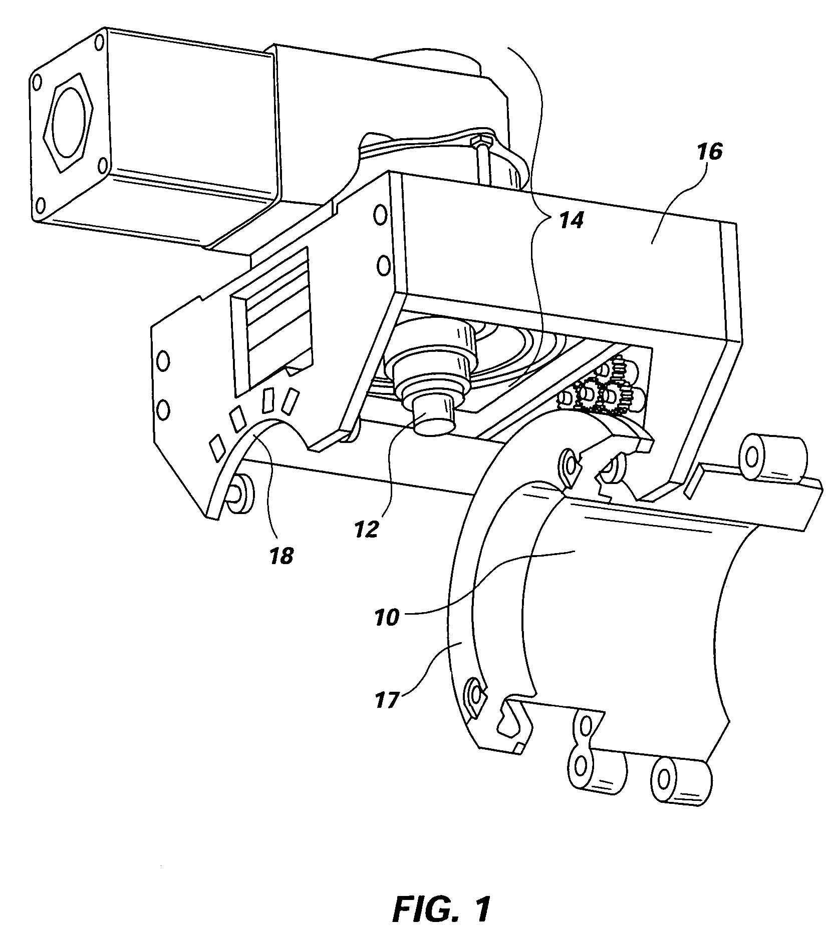
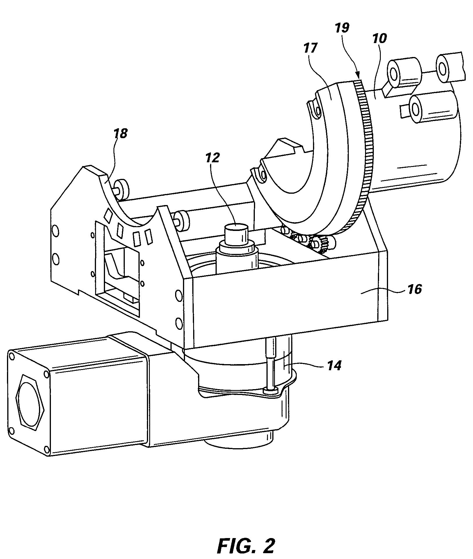
[0050]Reference will now be made to the drawings in which the various elements of the present invention will be given numerical designations and in which the invention will be discussed so as to enable one skilled in the art to make and use the invention. It is to be understood that the following description is only exemplary of the principles of the present invention, and should not be viewed as narrowing the claims which follow.

[0051]Friction stir welding of aluminum has been well established as a cost effective and high quality joining method. Further development of aluminum FSW has lead to joining aluminum pipe for specific applications. These methods and procedures have been published and documented but have little commercial value because of limited applications.

[0052]In contrast, steel pipe is widely used for a much greater variety of applications and for more critical purposes. Moreover, weld quality is critical to handle pressures, corrosive fluids, and prevent life threate...


PUM

PropertyMeasurementUnit
melting temperatureaaaaaaaaaa
forceaaaaaaaaaa
outer diameteraaaaaaaaaa

Abstract

A system and method for performing friction stir welding of non-planar materials having high melting temperatures, wherein a process is provided for performing longitudinal and radial welds on objects such as pipes, flanges, tanks, and shrouds, and wherein an active or passive mandrel provides support for the friction stir welding process.

Description

CROSS REFERENCE TO RELATED APPLICATIONS[0001]This document is a claims priority to the provisional patent application Ser. No. 60 / 443,801, filed Jan. 30, 2003.BACKGROUND OF THE INVENTION[0002]1. Field of the Invention[0003]This invention relates generally to friction stir welding (FSW) wherein heat for creating a weld is generated by plunging a rotating pin of a tool into a workpiece. More specifically, the present invention relates to a new tool and a new application of that tool when it is used in a friction stir welding process that enables the present invention to weld materials that are not functionally weldable using state of the art friction stir welding processes and tools, said materials including ferrous alloys such as stainless steel, and higher melting point super alloys that contain only small amounts of or no ferrous materials at all. The previously filed applications apply to making welds that are planar. However, this new process and apparatus enables friction stir w...

Claims


Application Information

Patent Timeline
Patent Type & Authority Patents(United States)
IPC IPC(8): B23K31/02B23KB23K20/12B23K20/227B23K37/00
CPCB23K20/1235B23K20/1255B23K20/126B23K37/0531B23K37/06B23K20/227B23K2203/04B23K2201/06B23K2101/06B23K2103/05
Inventor STEEL, RUSSELLNELSON, TRACY W.SORENSEN, CARL D.PACKER, SCOTT
Owner BRIGHAM YOUNG UNIV
Why Eureka
Try Eureka